


Reference Manual
00809-0400-4728, Rev AA
June 2011
Rosemount 644
A-16
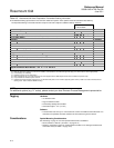
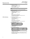
Standard FOUNDATION fieldbus Configuration
Unless otherwise specified, the transmitter will be shipped as follows for all
sensors:
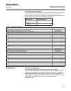
Custom Configuration
Custom configurations are to be specified when ordering. This configuration
must be the same for all sensors. The following table lists the necessary
requirements to specify a custom configuration.
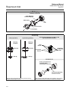
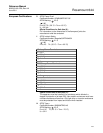
Final Station
AI Blocks are scheduled for 1 second. AI Blocks are linked as shown above.
Sensor Type: 4-wire Pt 100 ( = 0.00385) RTD
Damping: 5 seconds
Units of Measurement: °C
Line Voltage Filter: 50 Hz
Software Tag: See “Tagging” on page A-14
Function Blocks Tags:
• Resource Block: RB
• Transducer Block: TB
• LCD Block: LCD
• Analog Input Blocks: AI1, AI2
Alarm Range: 0
Alarm Limits of AI1 and AI2:
• HI-HI: 100 °C (212 °F)
• HI: 95 °C (203 °F)
• LO: 5 °C (41 °F)
• LO-LO: 0 °C (32 °F)
Local Display (when installed): Engineering Units of Temperature
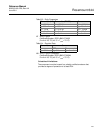
Option Code
Requirements/
Specification
C1: Factory
Configuration Data
(CDS required)
Date: day/month/year
Descriptor: 16 alphanumeric characters
Message: 32 alphanumeric character
Analog Output: Alarm and saturation levels
C2:Transmitter –
Sensor Matching
The transmitters are designed to accept Callendar-Van Dusen
constants from a calibrated RTD. Using these constants, the
transmitter generates a custom curve to match the
sensor-specific curve. Specify a Series 65, 65, or 78 RTD sensor
on the order with a special characterization curve (V or X8Q4
option). These constants will be programmed into the transmitter
with this option.
C4: Five Point
Calibration
Will include 5-point calibration at 0, 25, 50, 75, and 100% analog
and digital output points.
Use with Calibration Certificate Q4.
F6: 60 Hz Line Filter Calibrated to a 60 Hz line voltage filter instead of 50 Hz filter
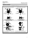
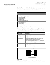
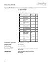
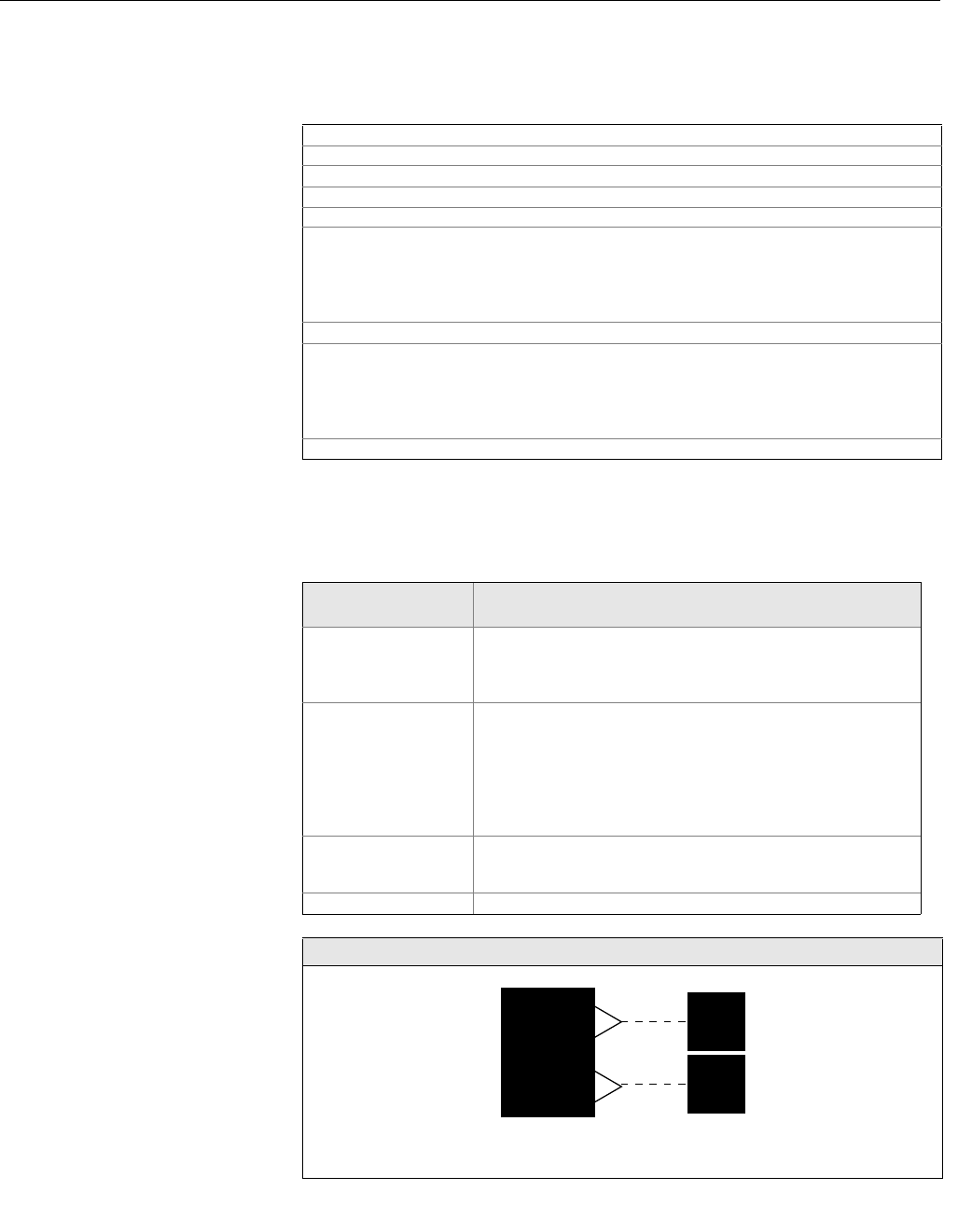
Standard Block Configuration
T
1
T
b
Note:
T
1
= Sensor Temperature
T
b
= Terminal Temperature
AI 1300
AI 1400