


Reference Manual
00809-0400-4728, Rev AA
June 2011
C-9
Rosemount 644
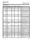
AI Parameter Table
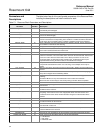
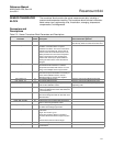
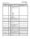
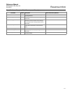
Table C-3. Definitions of Analog Input Function Block System Parameters
Parameter
Index
No.
Available Values Units Default Read/Write Description
ACK_OPTION 23 0 = Auto Ack Disabled
1 = Auto Ack Enabled
None 0 all Disabled Read and Write Used to set auto acknowledgment of alarms.
ALARM_HYS 24 0 – 50 Percent 0.5 Read and Write The amount the alarm value must return within
the alarm limit before the associated active alarm
condition clears.
ALM_SEL 38 HI_HI, HI, LO, LO_LO None Non selected Read and Write Used to select the process alarm conditions that
will cause the OUT_D parameter to be set.
ALARM_SUM 22 Enable/Disable None Enable Read and Write The summary alarm is used for all process
alarms in the block. The cause of the alert is
entered in the subcode field. The first alert to
become active will set the Active status in the
Status parameter. As soon as the Unreported
status is cleared by the alert reporting task,
another block alert may be reported without
clearing the Active status, if the subcode
has changed.
ALERT_KEY 04 1 – 255 None 0 Read and Write The identification number of the plant unit. This
information may be used in the host for sorting
alarms, etc.
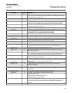
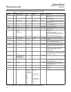
BLOCK_ALM 21 Not applicable None Not applicable Read only The block alarm is used for all configuration,
hardware, connection failure or system problems
in the block. The cause of the alert is entered in
the subcode field. The first alert to become active
will set the Active status in the Status parameter.
As soon as the Unreported status is cleared by
the alert reporting task, another block alert may
be reported without clearing the Active status, if
the subcode has changed.
BLOCK_ERR 06 Not applicable None Not applicable Read only This parameter reflects the error status
associated with the hardware or software
components associated with a block. It is a bit
string, so that multiple errors may be shown.
CAP_STDDEV 40 > = 0 Seconds 0 Read and Write The time over which the VAR_INDEX is
evaluated.
CHANNEL 15 1 = Pressure
2 = Housing
temperature
None AI
(1)
: Channel = 1
AI2: Channel = 2
Read and Write The CHANNEL value is used to select the
measurement value. Refer to the appropriate
device manual for information about the specific
channels available in each device.
You must configure the CHANNEL parameter
before you can configure the XD_SCALE
parameter.
FIELD_VAL 19 0 – 100 Percent Not applicable Read only The value and status from the transducer block
or from the simulated input when simulation is
enabled.
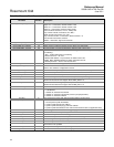
GRANT_DENY 12 Program
Tune
Alarm
Local
None Not applicable Read and Write Normally the operator has permission to write to
parameter values, but Program or Local remove
that permission and give it to the host controller
or a local control panel.
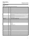
HI_ALM 34 Not applicable None Not applicable Read only The HI alarm data, which includes a value of the
alarm, a timestamp of occurrence and the state
of the alarm.
HI_HI_ALM 33 Not applicable None Not applicable Read only The HI HI alarm data, which includes a value of
the alarm, a timestamp of occurrence and the
state of the alarm.
HI_HI_LIM 26 Out_Scale
(2)
Out_Scale
(2)
Not applicable Read and Write The setting for the alarm limit used to detect the
HI HI alarm condition.
HI_HI_PRI 25 0 – 15 None 1 Read and Write The priority of the HI HI alarm.
HI_LIM 28 Out_Scale
(2)
Out_Scale
(2)
Not applicable Read and Write The setting for the alarm limit used to detect the
HI alarm condition.
HI_PRI 27 0 – 15 None 1 Read and Write The priority of the HI alarm.
IO_OPTS 13 Low Cutoff
Enable/Disable
None Disable Read and Write Allows the selection of input/output options used
to alter the PV. Low cutoff enabled is the only
selectable option.
L_TYPE 16 Direct
Indirect
Indirect Square Root
None Direct Read and Write Linearization type. Determines whether the field
value is used directly (Direct), is converted
linearly (Indirect), or is converted with the square
root (Indirect Square Root).