Reference Manual
00809-0400-4728, Rev AA
June 2011
Rosemount 644
C-10
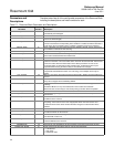
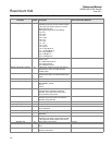
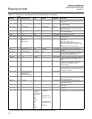
LO_ALM 35 Not applicable None Not applicable Read only The LO alarm data, which includes a value of the
alarm, a timestamp of occurrence and the state
of the alarm.
LO_LIM 30 Out_Scale
(2)
Out_Scale
(2)
Not applicable Read and Write The setting for the alarm limit used to detect the
LO alarm condition.
LO_LO_ALM 36 Not applicable None Not applicable Read only The LO LO alarm data, which includes a value of
the alarm, a timestamp of occurrence and the
state of the alarm.
LO_LO_LIM 32 Out_Scale
(2)
Out_Scale
(2)
Not applicable Read and Write The setting for the alarm limit used to detect the
LO LO alarm condition.
LO_LO_PRI 31 0 – 15 None 1 Read and Write The priority of the LO LO alarm.
LO_PRI 29 0 – 15 None 1 Read and Write The priority of the LO alarm.
LOW_CUT 17 > = 0 Out_Scale
(2)
0 Read and Write If percentage value of transducer input fails
below this, PV = 0.
MODE_BLK 05 Auto
Manual
Out of Service
None Not applicable Read and Write The actual, target, permitted, and normal modes
of the block.
Target: The mode to “go to”
Actual: The mode the “block is currently in”
Permitted: Allowed modes that target may take
on
Normal: Most common mode for target
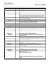
OUT 08 Out_Scale
(2)
± 10% Out_Scale
(2)
Not applicable Read and Write The block output value and status.
OUT_D 37 Discrete_State 1 – 16 None Disabled Read and Write Discrete output to indicate a selected alarm
condition.
OUT_SCALE 11 Any output range All available none Read and Write The high and low scale values, engineering units
code, and number of digits to the right of the
decimal point associated with OUT.
PV 07 Not applicable Out_Scale
(2)
Not applicable Read only The process variable used in block execution.
PV_FTIME 18 > = 0 Seconds 0 Read and Write The time constant of the first-order PV filter. It is
the time required for a 63% change in the IN
value.
SIMULATE 09 Not applicable None Disable Read and Write A group of data that contains the current
transducer value and status, the simulated
transducer value and status, and the
enable/disable bit.
ST_REV 01 Not applicable None 0 Read only The revision level of the static data associated
with the function block. The revision value will be
incremented each time a static parameter value
in the block is changed.
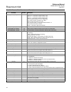
STATUS_OPTS 14 Propagate fault forward
Uncertain if Limited
Bad if Limited
Uncertain if Man Mode
0 Read and Write
STDDEV 39 0 – 100 Percent 0 Read and Write The average absolute error between the PV and
its previous mean value over that evaluation time
defined by VAR_SCAN.
STRATEGY 03 0 – 65535 None 0 Read and Write The strategy field can be used to identify
grouping of blocks. This data is not checked or
processed by the block.
TAG_DESC 02 32 text characters None none Read and Write The user description of the intended application
of the block.
UPDATE_EVT 20 Not applicable None Not applicable Read only This alert is generated by any change to the
static data.
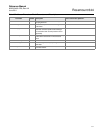
XD_SCALE 10 Any sensor range inH
2
O (68 °F)
inHg (0 °C)
ftH
2
O (68 °F)
mmH
2
O (68 °F)
mmHg (0 °C)
psi
bar
mbar
g/cm
2
kg/cm
2
Pa
kPa
torr
atm
deg C
deg F
AI1
(1)
: Customer
specification
or
inH
2
O (68 °F) for
DP/GP rng 1, 2, 3)
or
psi for DP/GP rng
4, 5 AP/644 all rng
AI2 deg C
In all Rosemount devices the units of the
transducer block is forced to match the unit code.
(1) The host system may write over default values pre-configured by Rosemount Inc.
(2) Assume that when L_Type = Direct, the user configures Out_Scale which is equal to XD_Scale
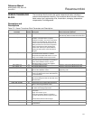
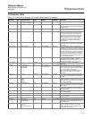
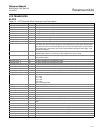
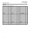
Table C-3. Definitions of Analog Input Function Block System Parameters
Parameter
Index
No.
Available Values Units Default Read/Write Description


