


Reference Manual
00809-0400-4728, Rev AA
June 2011
A-9
Rosemount 644
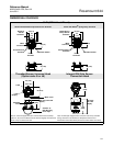
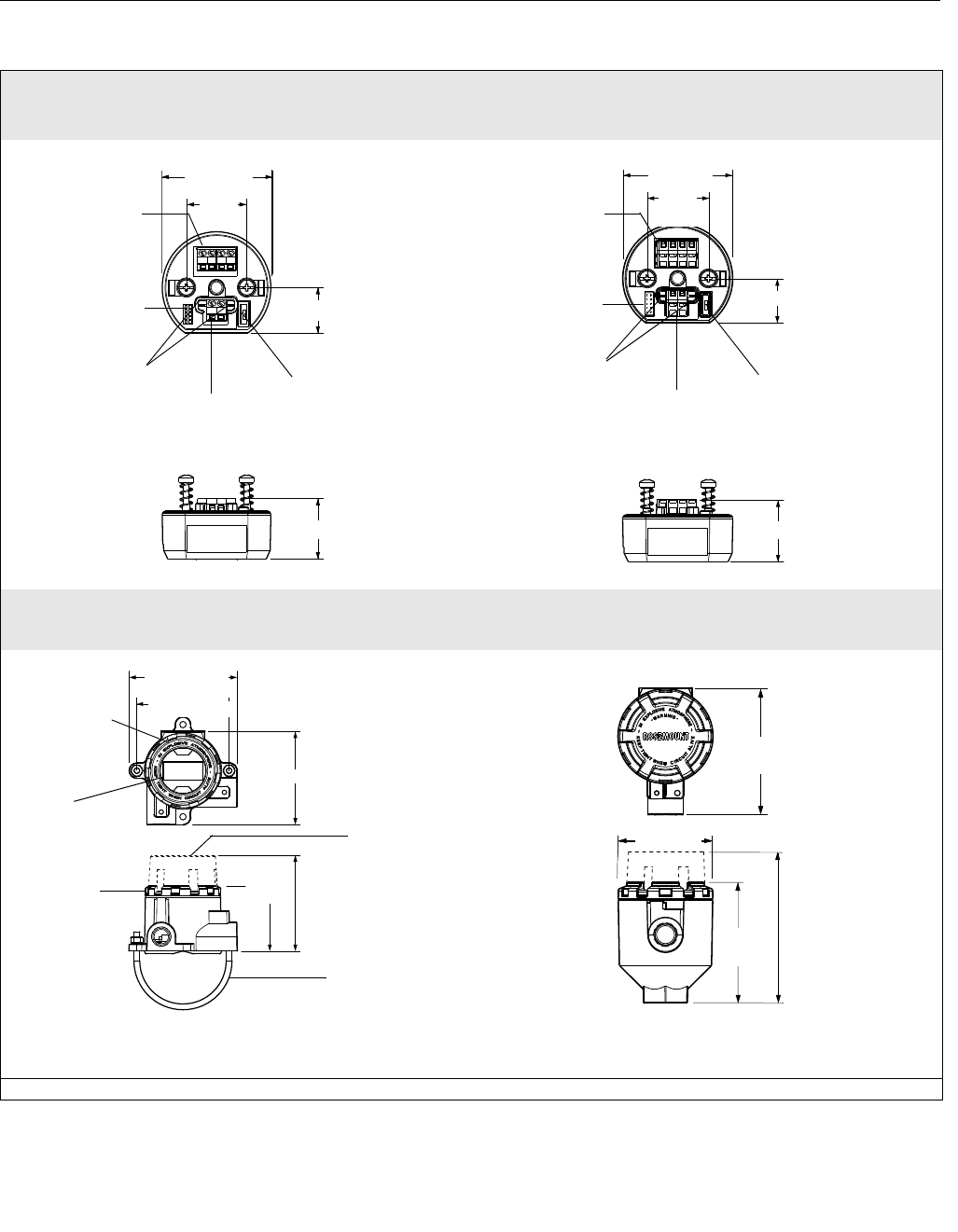
DIMENSIONAL DRAWINGS
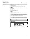
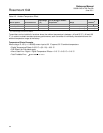
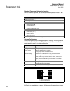
644H (DIN A Head Mount)
Shown with Standard Compression Screw Terminals
Shown with WAGO
®
Spring Clamp Terminals
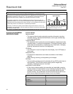
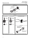
Threaded-Sensor Universal Head
(Option code J5 or J6)
Integral DIN Style Sensor
Connection Head
Note: A “U” Bolt is shipped with each universal head unless assembly
option X1, X2, or X3 is ordered. Since the head is integrally mounted to the
sensor, it may not need to be used.
Note: The DIN Style Integral sensor connection head is only available
through Volume 2 of the Rosemount Temperature Sensors and
Accessories Product Data Sheet (document number 00810-0101-2654).
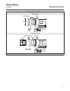
Dimensions are in millimeters (inches)
Simulation Switch
Standard
Sensor
Terminals
Communication
Terminals
60 (2.4)
33
(1.3)
Power
Terminals
33 (1.30)
24 (1.0)
Meter
Connector
33
(1.3)
60 (2.4)
34 (1.33)
WAGO Spring
Clamp Sensor
Terminals
24 (1.0)
Communication
Terminals
Simulation Switch
Meter
Connector
Power
Terminals
95 (3.74)
96 (3.76)
112 (4.41)
Meter Cover
316 SST “U”
Bolt Mounting,
2-inch Pipe
75
(2.93)
Label
Standard
Cover
LCD
Display
103 (4.03) with LCD
Display
78 (3.07)
128 (5.04)
with LCD
Display
100
(3.93)
104
(4.09)