


Reference Manual
00809-0400-4728, Rev AA
June 2011
2-11
Rosemount 644
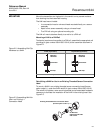
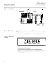
POWER SUPPLY FOUNDATION fieldbus Installation
Powered over F
OUNDATION fieldbus with standard fieldbus power supplies.
The transmitter operates between 9.0 and 32.0 Vdc, 11 mA maximum.
Transmitter power terminals are rated to 42.4 Vdc.
The power terminals on the 644 with F
OUNDATION fieldbus are polarity
insensitive.
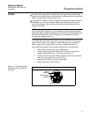
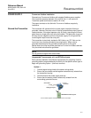
Ground the Transmitter The transmitter will operate with the current signal loop either floating or
grounded. However, the extra noise in floating systems affects many types of
readout devices. If the signal appears noisy or erratic, grounding the current
signal loop at a single point may solve the problem. The best place to ground
the loop is at the negative terminal of the power supply. Do not ground the
current signal loop at more than one point.
The transmitter is electrically isolated to 500 Vdc/ac rms (707 Vdc), so the
input circuit may also be grounded at any single point. When using a
grounded thermocouple, the grounded junction serves as this point.
Neither side of the loop should be grounded on F
OUNDATION fieldbus devices.
Only the shield wire should be grounded.
NOTE
Do not ground the signal wire at both ends.
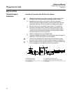
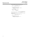
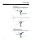
Ungrounded Thermocouple, mV, and RTD/Ohm Inputs
Each process installation has different requirements for grounding. Use the
grounding options recommended by the facility for the specific sensor type or
begin with grounding Option 1 (the most common).
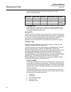
Option 1:
1. Connect signal wiring shield to the sensor wiring shield.
2. Ensure the two shields are tied together and electrically isolated from
the transmitter housing.
3. Ground shield at the power supply end only.
4. Ensure that the sensor shield is electrically isolated from the
surrounding grounded fixtures.
Connect shields together, electrically isolated from the transmitter
Shield ground point
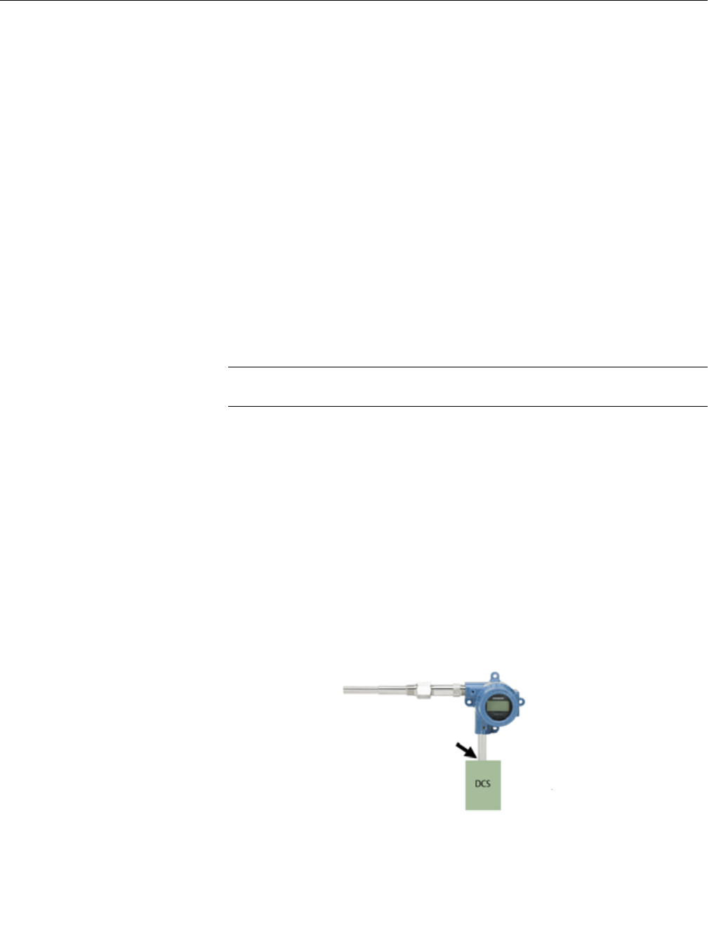
FOUNDATION Fieldbus segment
Transmitter
Sensor Wires