


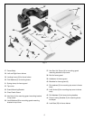

9
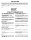
Fig. 14
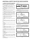
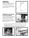
Fig. 16
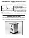
Fig. 17
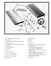
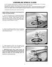
Fig. 18
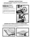
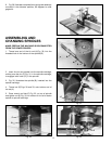
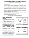
ASSEMBLING FENCE
TO SHAPER TABLE
1. The fence on this shaper can be mounted parallel
to the miter gage slot using two holes (B) Fig. 14, or
90 degrees to the miter slot by using two holes (A). The
following illustrates mounting the fence parallel to the
miter gage.
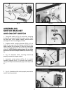
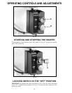
2. Place fence body (C) Fig. 15, on the table as shown,
and locate the two fence locking levers with washers (D)
and fence lock bars (E).
3. Fasten bar (E) to the front of the fence half using the
locking lever and washers (D), as shown in Figs. 16 and
17. Assemble the remaining bar to the other fence half in
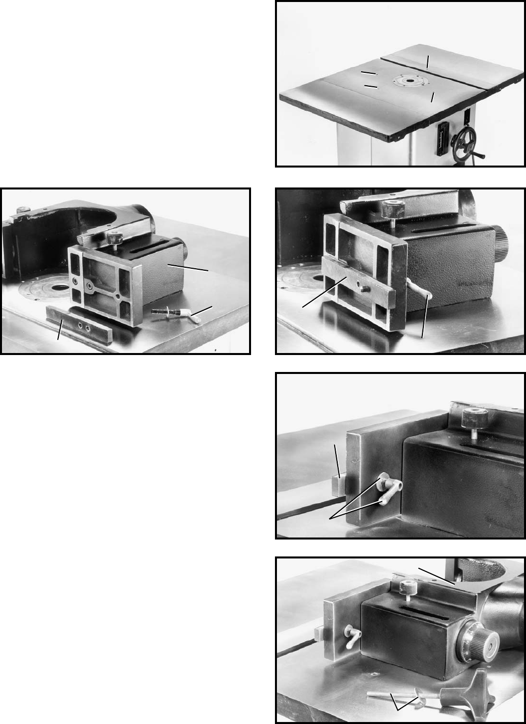
the same manner. NOTE: Locking levers (D) are spring-
loaded and can be repositioned by pulling out the
handle and repositioning it on the nut located
underneath the hub of the handle.
Fig. 15
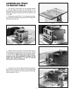
4. Locate the two fence locking handles and washers,
one of which is shown at (F) Fig. 18, and fasten fence
body (C) to one of the set of holes located on the shaper
table illustrated in Fig. 14.
A
B
A
B
C
E
E
D
E
D
C
F
D