


8
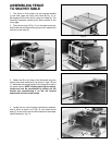
Fig. 9 Fig. 10
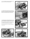
Fig. 11
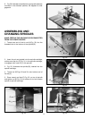
Fig. 13
Fig. 12
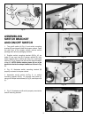
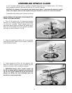
ASSEMBLING
SWITCH BRACKET
AND ON/OFF SWITCH
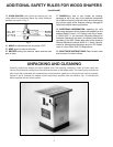
1. The on/off switch (A) Fig. 9, and switch mounting
bracket (B) are shipped inside the shaper cabinet. Open
the side door of the shaper cabinet, remove switch
package and remove packaging material.
2. Position switch mounting bracket (B) Fig. 10, so
holes (C) are over hole (D) in shaper cabinet (E), then
fasten bracket (B) to cabinet (E) using four truss head
screws (F) Fig. 9, flange nuts (G) and two switch adapter
plates (H). NOTE: Switch adapter plates (H) are to be
positioned inside the shaper cabinet as shown in Fig.
11.
3. Fig. 12, illustrates switch mounting bracket (B)
properly mounted to shaper cabinet.
4. Assemble on/off switch (A) Fig. 9, to switch
mounting bracket (B) Fig. 12, through two holes (J),
using two Phillips head screws (K) Fig. 9, and Keps nuts
(L).
5. Fig. 13, illustrates on/off switch properly mounted to
switch mounting bracket.
G
F
H
F
G
H
F
B
A
L
L
K K
B
D
E
C
C
H
H
B
J