


13
Fig. 34
Fig. 36 Fig. 37
Fig. 35
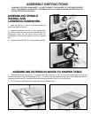
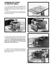
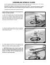
ASSEMBLING
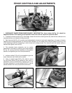
TABLE INSERTS
Three table inserts are provided for various size cutters,
as shown in Fig. 34. The large insert is adjustable and
should be set flush with the table as follows:
1. Remove the three slotted head screws (A) Fig. 34.
2. Using a screwdriver, turn the three adjusting screws
(B) Fig. 34, until insert is flush with table. Then replace
the slotted head screws (A).
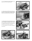
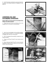
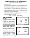
ASSEMBLING CUTTERS AND
COLLARS TO SPINDLE
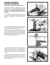
1. There are three different sized collars (A) Fig. 35,
supplied with the shaper. These collars will allow the
cutter and/or the 4-1/2" diameter spindle guard to be
positioned at various locations on the spindle.
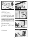
2. When assembling cutters to the spindle, it is
suggested that the cutter be positioned as close to the
bottom of the spindle as possible. This will reduce the
possibility of spindle run-out, which may effect the
finished appearance of the cut.
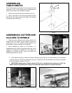
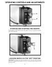
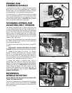
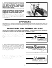
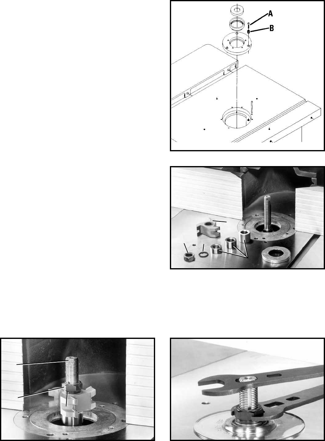
3. After determining if any collars are needed, assemble cutter (B) Fig. 35, keyed washer (C), and spindle
nut (D) as shown in Fig. 36, then place one wrench on flats (E) on top of spindle and one wrench on spindle
nut (D) and tighten as shown in Fig. 37.
4. IMPORTANT: Always place “keyed” washer (C) Fig. 36, on spindle before screwing on nut (D). The
“keyed” washer (C) prevents the nut (D), from loosening when spindle turns counterclockwise.
B
D
C
A
E
D
C