


22
Fig. 67 Fig. 68
Fig. 69
Fig. 70
Fig. 71
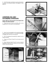
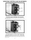
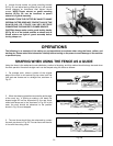
STARTING PIN
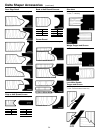
1. Your machine is supplied with a tapered starting pin
(A) Fig. 67, which is used as a support when starting the
cut. The starting pin (A) is placed on one of the tapered
holes (B) in the table.
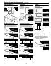
2. Fig. 68, illustrates starting pin (A) placed into hole in
table.
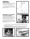
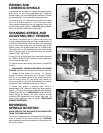
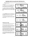
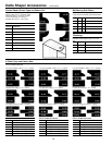
3. The work should be placed in the first position using
the guide pin as a support, as shown in Fig. 69. Then
swing the work into the cutter as shown in the second
position. The work will now be supported by the collar
and starting pin as shown in Fig. 69.
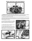
4. After the cut has been started, the work is swung
free of the starting pin and rides only against the collar
as shown in the third position Fig. 70. ALWAYS FEED
AGAINST THE ROTATION OF THE CUTTER.
IMPORTANT: If the work would be advanced to the
cutter without the side support of the starting pin, it
would invariably be kicked back.
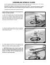
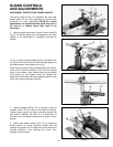
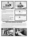
REPLACING SPINDLE CARTRIDGE
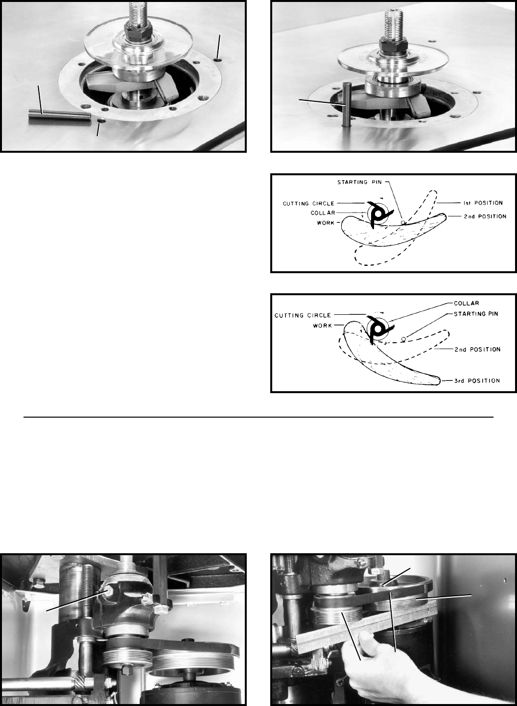
1. IMPORTANT: When replacing the spindle cartridge, bolt (A) Fig. 71, should only be tightened 7 to 10 foot pounds.
2. The spindle pulley (D) Fig. 72, and motor pulley (E), should always be aligned with each other to provide maximum
belt performance to reduce belt wear. To check pulley alignment, place a straight edge against the underside of, and
spanning both pulleys, as shown in Fig. 72. If an adjustment is necessary, loosen set screw (F) and move the motor up
or down until the two pulleys (D) and (E) are aligned.
3. Proper belt tension is attained when there is approximately 3/32" deflection using light finger pressure (approx. 3.5
lbs.) at the center of the belt span between pulleys (D) and (E) Fig. 72.
A
B
B
A
A
Fig. 72
F
E
G
D