


18
FENCE CONTROLS AND ADJUSTMENTS
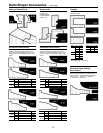
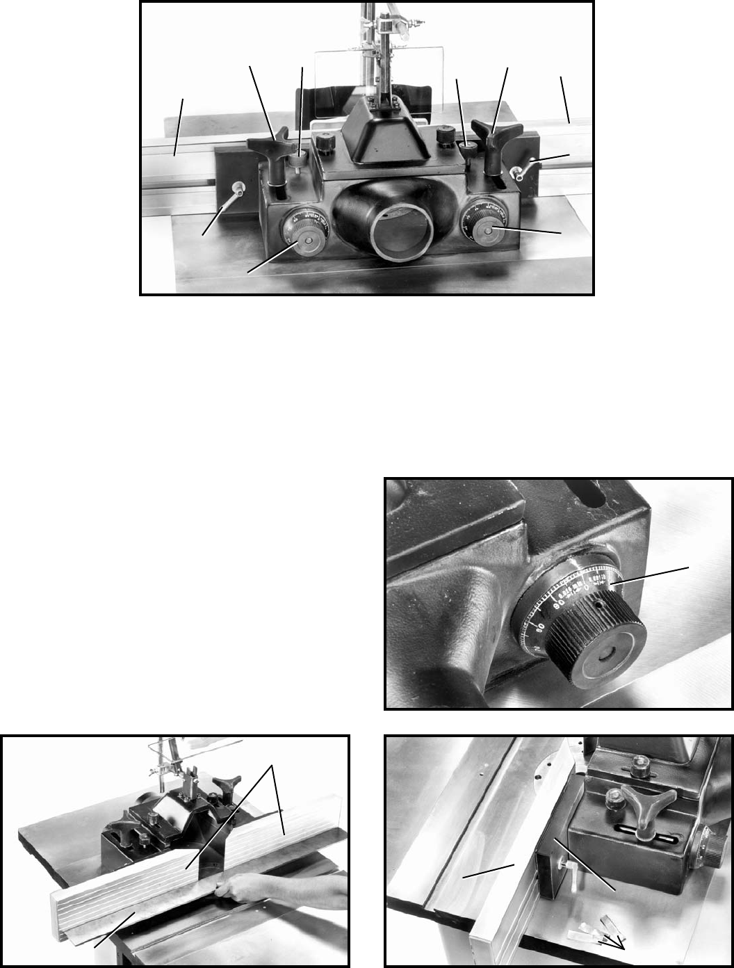
Fig. 50 Fig. 51
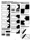
Fig. 49
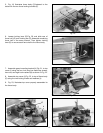
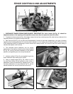
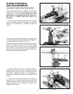
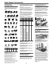
1. DISCONNECT SHAPER FROM POWER SOURCE. IMPORTANT: The fence halves (A) Fig. 48, should be
adjusted endwise so the opening at the spindle is never more than is required to clear the cutter.
2. To adjust the fence halves (A) Fig. 48 endwise, loosen the two fence locking levers (B), slide the fence halves to the
required positions, and tighten locking levers (B).
3. Each fence half (A) Fig. 48, can be moved independently, forward or backward, depending on the type of shaping
operation that is being performed. To move the fence halves in or out, loosen one of the lock knobs (C) and turn one
of the adjusting knobs (D), depending on which fence half is being moved. Turn knob (D) until the correct setting is
obtained and tighten lock knob (C).
Fig. 48
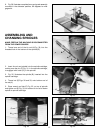
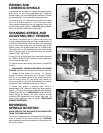
4. The complete fence assembly can be rapidly
positioned on the table by loosening two clamp handles
(E) Fig. 48, moving the fence assembly to the desired
position, and tightening the two clamp handles (E).
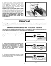
5. Indicator collars (F) Fig. 49, are supplied to give the
exact dimension each fence half is moved.
6. Using a straight edge (G) Fig. 50, check to see if
the two fence halves (H) are parallel to each other. If
parallelism cannot be achieved by adjusting one of the
two fence halves (H) in or out, shims (J) Fig. 51, can be
placed between the fence (H) and fence mount (K).
A
C
E
D
B
D
B
A
E
C
F
H
G
H
J
K