


19
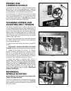
Fig. 53
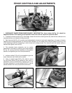
Fig. 54
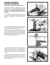
Fig. 55
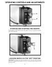
Fig. 52
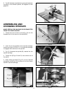
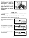
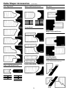
GUARD CONTROLS
AND ADJUSTMENTS
DISCONNECT SHAPER FROM POWER SOURCE.
The spring clamp (A) Fig. 52, holddown (B), and clear
plastic guard (C) are fully adjustable to provide safe
protection for most applications. NOTE: For certain
applications, the supplied spindle guard may have to
be used or a custom guard may need to be
fabricated.
1. Using a square (not shown), check to see if shaft (D)
Fig. 52, on spring clamp (A) is 90 degrees to the table
surface. If an adjustment is necessary, proceed as
follows:
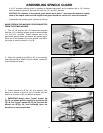
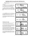
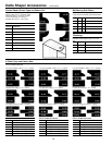
2. Adjust holddown (B) Fig. 55, by placing a piece of
material which will be used on the table as shown.
Loosen thumb screws on guard mounting bracket (K)
and adjust holddown (B) over top of workpiece to
provide some downward pressure and tighten thumb
screws.
3. Adjust clear plastic guard (L) Fig. 55, by loosening
thumb screws on guard mounting bracket (M) and
locating the guard so it will deflect the wood chips and
provide protection from reaching the cutter; then
retighten thumb screws.
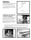
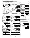
Lift up on guard locking handle (E) Fig. 53, loosen lock
nut (F) and turn screw (G) until shaft (D) is 90 degrees to
the table surface; then tighten lock nut (F).
Push down on guard locking handle (E) Figs. 53 and 54,
until it locks in place as shown in Fig. 54. If the locking
action is too loose or tight, loosen screw (H) and adjust
cam washer (J), then tighten screw (H). Repeat this
adjustment on the screw and cam washer located on the
other side of guard locking handle (E).
C
D
A
B
E
F
G
H
J
E
K
L
M
B
D