


12
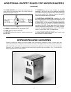
Fig. 29
Fig. 30
Fig. 31
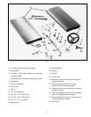
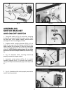
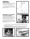
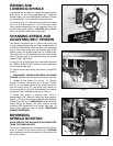
6. Fig. 29, illustrates complete fence and guard assembly
mounted in the alternate position, 90 degrees to miter
gage slot.
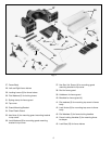
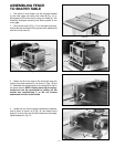
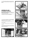
ASSEMBLING AND
CHANGING SPINDLES
MAKE CERTAIN THE MACHINE IS DISCONNECTED
FROM THE POWER SOURCE.
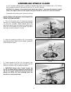
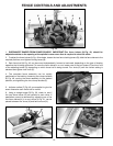
1. Thread one end of the tie rod (A) Fig. 30, into the
threaded hole in the bottom of the spindle (B).
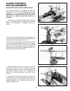
2. Insert tie rod and spindle into the spindle cartridge,
making sure the pin (C) Fig. 31, in the spindle cartridge,
is engaged with notch (D), in the spindle.
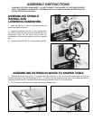
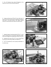
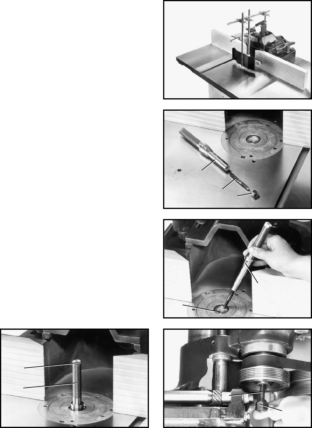
3. Fig. 32, illustrates the spindle (B), inserted into the
spindle cartridge.
4. Thread nut (E) Figs. 30 and 33, onto bottom end of
tie rod (A).
5. Place wrench on flats (F) Fig. 32, on top of spindle
and tighten nut (E) Fig. 33, on bottom of tie rod to fasten
spindle to spindle cartridge.
Fig. 32 Fig. 33
A
B
D
C
F
B
A
E
E