


17
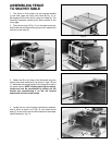
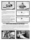
Fig. 45
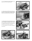
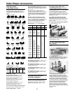
Fig. 46
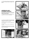
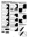
Fig. 47
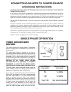
RAISING AND
LOWERING SPINDLE
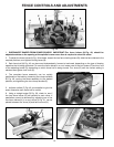
The spindle can be raised or lowered by loosening lock
knob (A) Fig. 45, and turning handwheel (B). To raise the
spindle height, turn the handwheel (B) clockwise. To lower
the spindle height, turn handle (B) counterclockwise.
The scale (C) Fig. 45, indicates the spindle travel range
from 0 to 3" and is marked in 1/16" increments. Minor
cutter height adjustments can be measured using the
pointer (D) along the scale (C). CAUTION: Always tighten
lock knob (A) after adjusting spindle height.
CHANGING SPEEDS AND
ADJUSTING BELT TENSION
The shaper is supplied with a 2-step motor pulley and
a 2-step spindle pulley that provides spindle speeds of
7,000 and 10,000 R.P.M. When the belt is on the largest
step of the motor pulley and the smallest step of the
spindle pulley, the spindle speed will be 10,000 R.P.M.
When the belt is on the smallest step of the motor pulley
and the largest step of the spindle pulley, the spindle
speed will be 7,000 R.P.M.
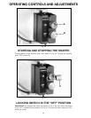
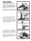
A chart (Y) Fig. 46, illustrating the correct belt placement
for 7,000 or 10,000 R.P.M. is located on the inside panel
of the motor access door.
To change speeds and adjust belt tension, proceed as
follows:
1. DISCONNECT THE MACHINE FROM THE POWER
SOURCE and open motor access door, as shown in Fig. 46.
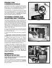
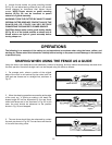
2. Loosen thumb screw lock (A) Fig. 47. Release
tension on belt by moving lever (B), to the left. Position
belt (C), on the desired steps of the spindle pulley (D),
and the motor pulley (E), and apply belt tension by
moving lever (B), to the right. When desired belt tension
is applied to belt, retighten thumb screw lock (A).
3. Proper belt tension is attained when there is
approximately 3/32" deflection using light finger pressure
(approx. 3.5 lbs.) at the center of the belt span between
pulleys (D) and (E) Fig. 47. IMPORTANT: Pulleys (D) and (E)
should always be aligned with each other to provide
maximum belt performance and reduce belt wear. To
check pulley alignment, refer to section “REPLACING
SPINDLE CARTRIDGE.”
REVERSING
SPINDLE ROTATION
MAKE CERTAIN THE MACHINE IS DISCONNECTED
FROM THE POWER SOURCE.
The motor is equipped with a reversing switch (X) Fig. 46,
which is located on the motor junction box. CAUTION:
Never attempt to reverse the rotation of the spindle with
the motor running.
X
Y
D
C
A
B
C
E
D
B
A