


7
ASSEMBLY INSTRUCTIONS
WARNING: FOR YOUR OWN SAFETY, DO NOT CONNECT THE SHAPER TO THE POWER SOURCE
UNTIL THE SHAPER IS COMPLETELY ASSEMBLED AND YOU HAVE READ AND UNDERSTOOD THE
ENTIRE INSTRUCTION MANUAL.
Fig. 5
Fig. 6
Fig. 8Fig. 7
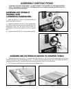
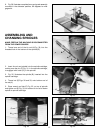
ASSEMBLING SPINDLE
RAISING AND
LOWERING HANDWHEEL
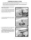
1. Insert key (A) Fig. 5, into slot in spindle raising and
lowering shaft (B) as shown.
2. Assemble handwheel (C) Fig. 5, onto spindle shaft
(B), making certain the key (A) fits into the slot (D) in the
handwheel. Insert the set screw which holds the
handwheel to the shaft and tighten screw firmly against
key.
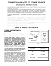
3. Thread lock knob (E) Fig. 6, into the spindle shaft (B).
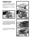
ASSEMBLING EXTENSION WINGS TO SHAPER TABLE
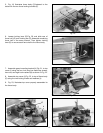
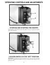
1. Assemble extension wing (A) Fig. 7, to shaper table (B) using three 1-1/4" inch-long hex head screws (C) and flat
washers (D) supplied. Use a straight edge (E) Fig. 7, to make certain the extension wing is level with shaper table before
tightening three screws (C). Assemble and level remaining extension wing in the same manner.
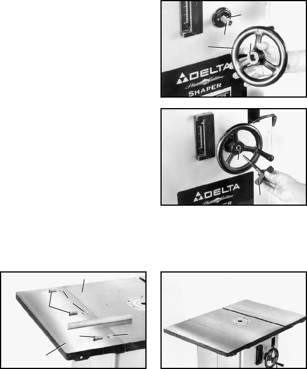
2. Fig. 8, illustrates both extension wings assembled to shaper table.
A
B
C
D
B
E
D
C
A
C
D
B