


20
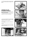
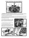
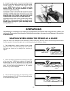
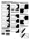
Fig. 56
4. Loosen thumb screws on guard mounting bracket
(P) Fig. 56, and adjust spring clamp (N) so it will provide
inward pressure on workpiece; then tighten thumb
screws. NOTE: Thumb screws on guard mounting
bracket (R) Fig. 56, can be loosened to permit
extension of guard assembly.
WARNING: TURN THE CUTTER BY HAND TO MAKE
CERTAIN CUTTER DOES NOT CONTACT ANY OF THE
GUARDING OR FENCE HALVES BEFORE
CONNECTING THE SHAPER TO POWER SOURCE.
CAUTION: Always make certain guard locking handle
(E) Fig. 56, is in the locked position as shown and all
thumb screws are tight on guard assembly before
turning shaper on.
OPERATIONS
The following is an example of the setting up and operational procedures when using the fence, collars, and
starting pin. Please review this information carefully before turning on the power to avoid damage to the machine
or personal injury.
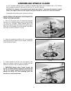
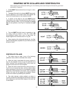
SHAPING WHEN USING THE FENCE AS A GUIDE
Using the fence is the safest and most satisfactory method of shaping, and this method should always be used when
the work permits. Almost all straight work can be shaped using the fence as follows:
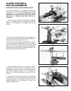
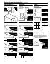
Fig. 57
Fig. 59
Fig. 58
1. For average work, where a portion of the original
edge of the work is not touched by the cutter, both the
front and rear fences are in a straight line, as shown in
Fig. 57.
2. When the shaping operation removes the entire edge
of the work, e.g., in jointing or making a full bead, the
shaped edge will not be supported by the rear fence
when both fences are in line, as shown in Fig. 58. In this
case, the work should be advanced to the position
shown in Fig. 58, and stopped.
3. The rear fence should then be advanced to contact
the work, as shown in Fig. 59. The rear fence will then be
in line with the cutting circle.
R
E
P
N