


24 25
24 25
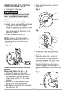
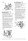
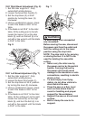
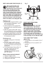
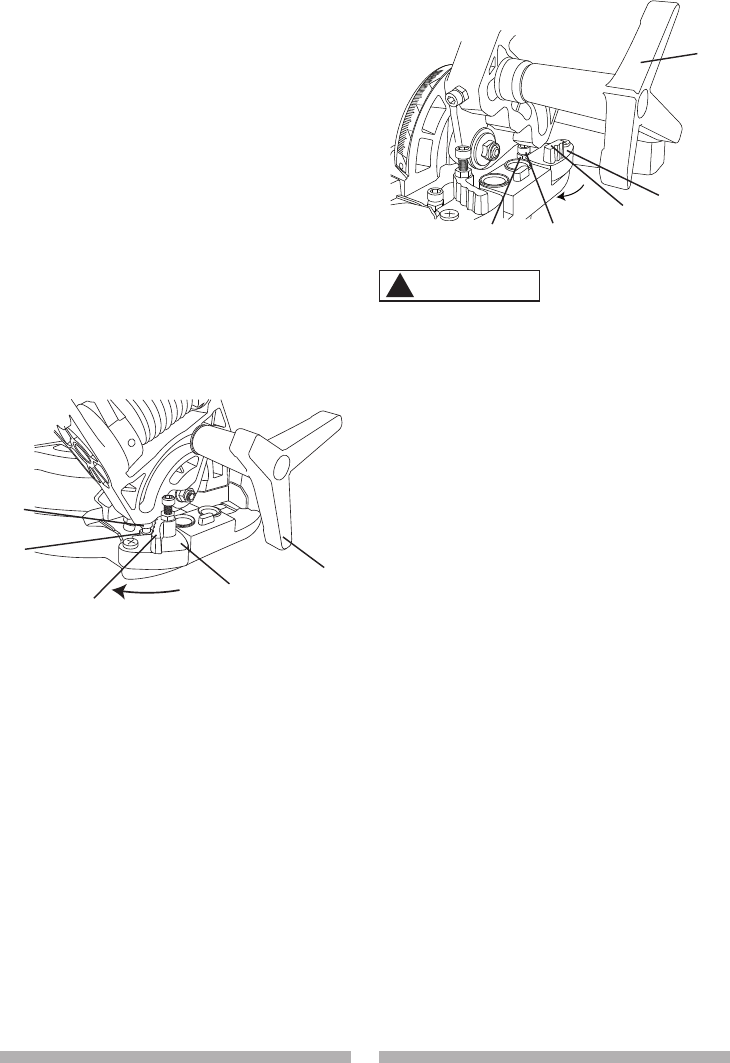
33.9° Right Bevel Adjustment (Fig. S)
1. Set the miter angle to 0°. Fully
extend both sliding fences.
2. Loosen the bevel lock handle (1).
3. Set the stop block (2) at 33.9°
position by turning the lever (3)
clockwise.
4. Using a combination square, check
to see if the blade is 33.9° to the
table.
5. If the blade is not 33.9°
to the miter
table, tilt the cutting arm to the left,
loosen the locknut (4) on the stop
block (2), and turn the bolt (5) in or
out with a hex wrench until the blade
is 33.9° to the table.
Fig. S
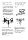
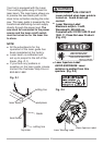
33.9° Left Bevel Adjustment (Fig. T)
1. Set the miter angle to 0°. Fully
extend both sliding fences.
2
. Loosen the bevel lock handle (1).
3. Set the stop block at 33.9° position
by turning the lever (2) clockwise.
4. Using a combination square, check
to see if the blade is 33.9° to the
table.
5. If the blade is not 33.9°
to the miter
table, tilt the cutting arm to the right,
loosen the locknut (3) on the stop
block (5), and turn the bolt (4) in or
out with a hex wrench until the blade
is 33.9° to the table.
Fig. T
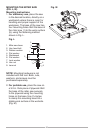
To avoid injury from unexpected
saw movement:
Before moving the saw, disconnect
the power cord from the outlet and
lock the cutting arm in the lower
position using the stop latch.
NOTE: The stop latch is for carrying
or storing the tool. It is NOT to be
used for holding the saw while
cutting.
● Never carry the miter saw by
the power cord or by the switch
handle. Carrying the tool by
the power cord could cause
damage to the insulation or wire
connections, resulting in electric
shock or fire.
● To avoid injury from flying
debris, do not allow visitors to
stand behind the saw.
● Place the saw on a firm, level
work surface where there is
room for handling and proper
support for the workpiece.
● Support the saw on a level work
surface.
● Bolt or clamp the saw to its
support.
1
4
3
2
5
1
2
3
4
5
WARNING
!