T190 Compact Track Loader
Operation & Maintenance Manual 24
HYDRAULIC CONTROLS (CONT’D)
High-Flow Hydraulics Operation (If Equipped)
(Cont’d)
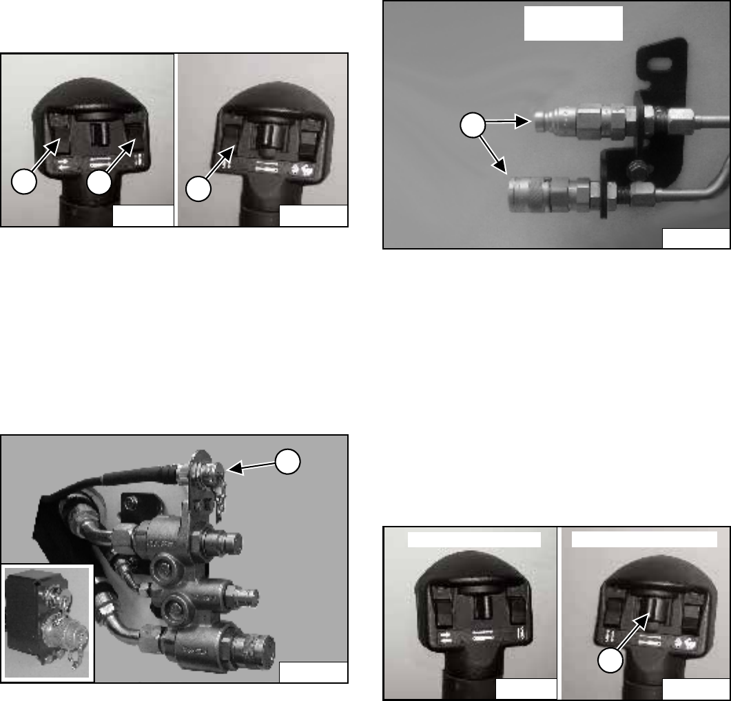
Figure 47
You can use additional switches (1, 2 and 3) [Figure 47]
on the right and left control handles for functions which
control some attachments.
See the appropriate Attachment Operation &
Maintenance Manual for control details.
Attachment Control Device (ACD) (If Equipped)
Figure 48
You will need the Dual-Connector (7-pin / 14-pin) kit (1)
[Figure 48] to operate early model attachments. See
your Bobcat Loader dealer.
Secondary Front Auxiliary Hydraulics (If Equipped)
Figure 49
The secondary front auxiliary quick couplers (1)
[Figure 49] are available a Field Installed Accessory.
These are used when there is a need for additional
auxiliary hydraulics (EXAMPLE: Planer side shift).
Connect the attachment to the secondary auxiliary
hydraulics (1) [Figure 49].
Set the Auxiliary Hydraulic Button for Variable Flow or
Maximum Flow Only. (See Auxiliary Hydraulics Operation
(VARIABLE FLOW) on Page 21) or (See Auxiliary
Hydraulics Operation (MAXIMUM FLOW ONLY) on
Page 21).
Figure 50
Push switch (1) [Figure 50] to the right or left to change
fluid flow direction. (EXAMPLE: Side shift on the Planer.)
NOTE: The secondary front auxiliary hydraulics and
the rear auxiliary hydraulics operate from the
same auxiliary section of the control valve. To
operate only one of these auxiliary functions,
disconnect the other.
P-54602
3
P-54603
1
2
P-43614
1
P-19820
P16291A
1
SECONDARY
COUPLERS
P-54602
Right Steering Lever
1
P-54603
Left Steering Lever


