T190 Compact Track Loader
5 Operation & Maintenance Manual
INSTRUMENT PANEL IDENTIFICATION
Left Panel
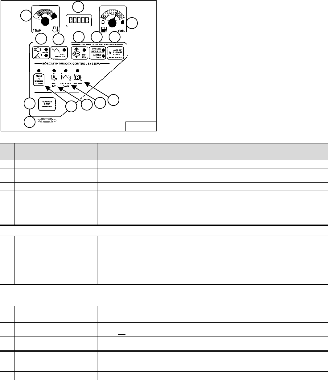
Figure 5
The left instrument panel is the same for both the Key
Switch and Keyless Instrument Panels [Figure 5].
The table below shows the DESCRIPTION and
FUNCTION / OPERATION for each of the components of
the left panel.
* See SYSTEM SETUP & ANALYSIS, Page 110 for further description of SERVICE CODES.
B-15551
1
4
5
6 7 8
3
2
14
13
9
10
11
12
REF.
NO
DESCRIPTION FUNCTION / OPERATION
1 TEMPERATURE GAUGE Shows the engine coolant temperature.
2 HOURMETER / CODE DISPLAY /
GLOW PLUG COUNTDOWN
HOURMETER - Records operating hours of loader. CODE DISPLAY - Display numeric SERVICE CODES*
relating to the loader monitoring system. COUNTDOWN - Preheat time remaining
3 FUEL GAUGE Shows the amount of fuel in the tank.
4 LIGHTS / HOLD FOR CODES LIGHTS - Press once for FRONT LIGHTS. Press a second time for FRONT AND REAR lights. Press a third time
to turn all lights off. HOLD FOR CODES - Press and hold two seconds for display of SERVICE CODES (2).
(CODES* show only when there is an error found by loader monitoring system.)
5 BUCKET POSITIONING (Option) Press to engage the BUCKET POSITIONING function. Press again to disengage. Press and hold 2 seconds to
view SHTDN (SHUTDOWN) feature & Operational Code Number in HOURMETER / CODE DISPLAY.
ATTACHMENT AUXILIARY HYDRAULICS
6 HIGH FLOW (Option) Press to engage the HIGH FLOW auxiliary hydraulics. Press again to disengage.
7 MAXIMUM FLOW / VARIABLE FLOW Press once to engage the VARIABLE FLOW auxiliary hydraulics. Press a second time to engage MAXIMUM
FLOW. Press a third time to disengage all auxiliary hydraulics. [VARIABLE FLOW allows for slow-to-fast
movement of auxiliary functions. (The farther you move the switch, the faster the movement of auxiliary
functions.) MAXIMUM FLOW allows for only fast movement.]
8 AUXILIARY PRESSURE RELEASE Rear Auxiliary Only - With key ON or engine running, press and hold button for 5 seconds. (See Relieve
Hydraulic Pressure (Loader And Attachment) on Page 23 for front auxiliary pressure release.)
BOBCAT INTERLOCK CONTROL SYSTEM (BICS)
(See SYSTEM ANALYSIS, Page 109 for more information.)
9 PRESS TO OPERATE LOADER Press to activate BICS System when the Seat Bar is down and operator is seated in operating position.
10 SEAT BAR The light comes ON when the seat bar is down.
11 LIFT & TILT VALVE The light comes ON when the seat bar is down and the PRESS TO OPERATE Button is pressed. The lift and tilt
functions can be operated when the light is ON.
12 TRACTION The light comes ON when the seat bar is down, engine is running, and parking brake is released. The loader can
be moved forward or backward when the light is ON.
13 TRACTION LOCK OVERRIDE (Function Only When Seat Bar Is Raised And The Engine Is Running) Press to unlock the brakes. Allows you to
use the steering levers to move the loader forward or backward when using the backhoe attachment or for loader
service. (See TRACTION LOCK OVERRIDE on Page 12). Press a second time to lock the brakes.
14 ALARM The ALARM beeps when there is an Error, WARNING or SHUTDOWN condition.


