


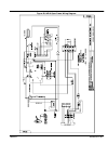
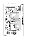

Series AE11 C-3MN2415
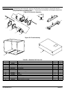
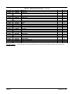
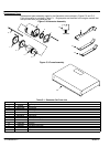
Table C-1 Generator Set Parts List Continued
Ref No. Part No. Description
Not Shown EH0491A02 Enclosure, Top
Not Shown EH0491A11 Enclosure, Access Panel
Not Shown EH0491A01 Enclosure, Front
Not Shown EH0491A10 Enclosure, Right Side (Hinge) & Rear
Not Shown EH0491A13 Enclosure, Left Side (Latch) & Front
Not Shown HB2414A05 Latch
Not Shown HW2409A21 Hinge, Nylon
Not Shown HW2409A22 Hinge, Nylon
Not Shown HW2410A02 Gas Spring, 30 lb.
Not Shown EH0309A02 Control Box
Not Shown EM0046A00 Engine Controller, 4110 Auto Start
Not Shown RE5031A01 Relay
Not Shown EM0027A01 Voltage Regulator (AVC63−20.)
Not Shown CK0070A29 Circuit Breaker 50Amp
Not Shown FU066A02 Fuse, AGC1
Not Shown FU066A00 Fuse, MTH−5
Not Shown SE0057A02 Solenoid, Engine Starting 12V
Not Shown EA5038A00 Muffler
Not Shown HB6116A00 Battery Tie Down
Not Shown HA3187A12 Battery Tie Down Bolt
Not Shown EA0010A04 Battery Charger, 12V, 2AMP
Not Shown EA0000A00 Regulator, K−N, Manual Prime
Not Shown SE0071A00 Solenoid, Automatic Gas Valve
Conversion from LPG to Natural Gas Optional Procedure
If this is a new installation, begin with step 5.
If the generator has been installed, ensure that the following steps are performed:
1. Place the controller in the OFF position.
2. Place the circuit breaker in the OPEN position.
3. Turn off the LPG supply.
Disconnect and remove the LPG equipment and hoses.
4. Disconnect the negative terminal from the starting battery.
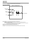
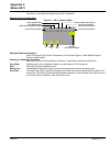
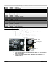
Figure C-4
90° Elbow
K−N Regulator
Insert
5. Open the lid and remove the front panel by removing the two 7/16” bolts along the top
edge of the front panel.
6. Remove the hose that connects to the 90° elbow at the top of the demand (K−N)
regulator, Figure C-4.