


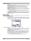

Troubleshooting and Maintenance 5-3MN2415
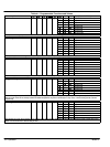
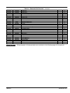
Table 5-2 Troubleshooting Guide (Digital Controller Only)
Problem Possible Cause Remedy
Controller does not power up even with
correct DC power applied
Wiring Mistake
Loss of DC Supply
Check the battery and wiring to the unit. Check the DC supply.
Check the DC fuse.
Check DC supply voltage is not above 35 Volts or below 9 Volts.
Check the operating temperature is not above 70 °C.
Low Oil Pressure fault Low Oil Pressure
Defect in sender or wiring
Check engine oil pressure.
Check oil pressure switch and wiring.
Check switch polarity (i.e. Normally Open or Normally Closed).
High Engine Temperature fault Excessive Temperature
Defect in sender or wiring
Check engine temperature.
Check switch and wiring.
Check switch polarity (i.e. Normally Open or Normally Closed).
Shutdown fault Fault Trip
Failed switch or wiring
Clear trip condition and reset controller.
Check switch and wiring of fault indicated by the LED.
Check configuration of input.
Fail to Start is activated after pre−set
number of attempts to start
No fuel
No starting current to starter motor
Engine fault
Check fuel solenoid is on and battery supply is present at solenoid.
Check fuel.
Check battery supply.
Refer to engine manual.
Continuous starting of generator in AUTO Remote Start circuit fault Check that there is no signal present on the Automatic start" input.
Generator fails to start at remote start
command
No Remote Start Signal
Wrong generator mode
Check the Remote Start" input signal.
Check that the Auto Start" mode is selected.
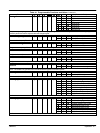
Pre−heat inoperative Check wiring to engine heater plugs.
Check battery supply is present at the Pre−heat output of module.
Check pre−heat has been selected in your configuration.
NB all the outputs are negative switching.
Starter motor inoperative Check wiring to starter solenoid.
Check battery supply.
Check battery supply is present on the Starter output of module.
NB all the outputs are negativeswitching.
Fuel solenoid inoperative Check wiring to fuel solenoid.
Check battery supply.
Check battery supply is present on the fuel output of module.
NB all the outputs are negativeswitching.
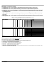
Note: Table 5-2 is provided as a guide check−list only. It is possible for the module to be
configured to provide a wide range of different features always refer to the source of your
module configuration if in doubt.
Note: All the outputs are solid state, rated at 1.2 Amps and switch to battery negative when
active.