


Operation 4-9MN2415
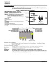
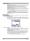
Electrical Connections
The engine controller is installed into the AE11 from the factory. The information provided here
will help you connect external devices to the Auxiliary inputs and outputs.
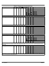
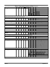
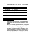
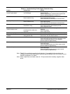
Table 4-2 Engine Controller Terminal Identification
Pin No Description Cable Size Notes
1 DC Plant Supply Input (−ve) 1.0mm Connected to plant battery negative
2 DC Plant Supply Input (+ve) 1.0mm Connected to plant battery positive (Recommended Fuse 2A)
3 Fuel Solid State Output 1.0mm Used to operate the fuel relay.
4 Start Solid State Output 1.0mm Used to operate the cranking relay.
5 Auxiliary Solid State Output 11.0mm Configurable output.
6 Auxiliary Solid State Output 21.0mm Configurable output.
7 Charge Fail Input/ Excitation Output 1.0mm Must NOT be connected to plant supply negative if not used.
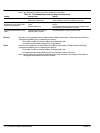
8 Low Oil Pressure Input 0.5mm Switch to negative.
9 High Engine Temp Input 0.5mm Switch to negative.
10 Auxiliary Input 10.5mm Switch to negative.
11 Auxiliary Input 20.5mm Switch to negative.
12 Automatic start Input 0.5mm Switch to negative.
13 Not used
14 Not used
15 Functional Earth 1.0mm Connect to a good clean earth point.
16 Not used
17 Not used
18 Not used
19 Not used
20 Alternator Input L1 1.0mm Do not connect if not used. (2A Fuse)
21 Alternator Input N 1.0mm Do not connect if not used.
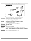
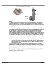
Garretson Model KN Fuel Valve Considerations
General
The KN is designed for sensitivity and simple operation. It is used with low−pressure vaporized
gaseous fuels, where dependable starting is a requirement. Because of its extreme sensitivity,
the KN offers excellent results in most remote starting applications (Standby power generators,
etc.). With proper installation and maintenance, the KN will provide years of trouble−free service.
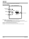
Operation
The KN is an atmospheric zero governor which acts like the float and needle valve in a gasoline
carburetor. Air−flow through a venturi in the carburetor creates a vacuum, which acts through the
outlet of the KN on the diaphragm. Atmospheric pressure then forces the diaphragm toward the
vacuum, depressing the lever and pulling the valve seat away from the orifice, which allows fuel
to flow as long as the demand persists. When the vacuum ceases, a spring force pushes on the
lever and forces the valve seat against the orifice shutting off the fuel flow. It is important to
remember that fuel should not flow through the KN when the engine is not running.
A properly adjusted KN requires a vacuum of only 0.25” to 0.35” of water column to start the
opening sequence. Due to this sensitivity, most installations do not need priming to start unless
low cranking speeds or restricted and lengthy piping are required. If priming is necessary and a
manual primer is installed, use only 1 or 2 second bursts of fuel and immediately try to start the
engine. If there is a choke on the carburetor, do not use it as this will probably cause flooding and
hard starting. As you can see, the operation of this unit is simple and basic. If you are having
trouble operating the engine, in most cases the fuel controller is not malfunctioning. There is
generally a problem with the engine or fuel supply. so do not make adjustments or attempt to
service the KN until you are sure it is needed.