


3-10 Receiving & Installation MN2415
AE10 Electrical Connections Applies only to AE10 Enclosed and Open Series Generators
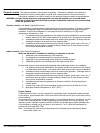
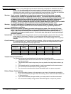
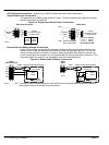
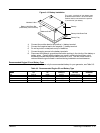
Single Phase Power Connections
The generator has a 240V single phase AC output. These connections are made at the power
terminal box shown in Figure 3-5.
Figure 3-5 Single Phase Output Power Connections
1
N
AE10 Open
AE10 with Enclosure
4
Generator
Output
Customer
AC Output Connections
(to Transfer Switch)
L1
L2
N
L1 to N
L2 to N
L1 to L2
120VAC
120VAC
240VAC
1
N
4
Generator
Output
Customer
AC Output Connections
(to Transfer Switch)
L1
L2
N
L1 to N
L2 to N
L1 to L2
120VAC
120VAC
240VAC
G
To Frame
Note: G and N are internally
tied to Frame Ground.
BW0333D
BW0201D
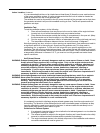
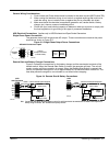
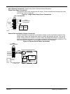
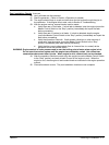
Remote Start and Battery Charger Connections
Figure 3-6 shows the connections for the battery charger and the remote start contacts of the
transfer switch. When the Remote Start Switch is closed, the generator will start. The unit will
remain running until this connection is opened. When the Remote Start Switch is opened, the
control circuits allow the engine to run for approximately 60−90 seconds before it shuts off. This
time delay allows the engine to run unloaded to cool down before stopping.
Figure 3-6 Remote Start & Battery Connections
R1
R2
Batt+
Batt−
D1
D2
AE10
with Enclosure
Remote Start Switch
(Close to Start)
Customer Provided Optional Equipment
Twisted Pair Wire
Battery
Charger
Out+
Out−
To 120VAC
(Shore Power)
AE10
Open
Remote Start Switch
(Close to Start)
Customer Provided Optional Equipment
Twisted Pair Wire
Battery
Charger
Out+
Out−
To 120VAC
(Shore Power)
Connect DK1 and DK2 of the battery charger go to the D1 and D2 terminals of the terminal block if a Master Control Systems Inc.
Battery charger is installed. DK1 and DK2 are not polarity sensitive.
Note:
Battery
+−
BW0333D
BW0201D
16AWG
16AWG