43
Chapter 2: Task Guide
To select transitional timing or store qualified
Selecting the State Mode (Synchronous
Sampling)
In state mode, the logic analyzer samples synchronously, based on a
sampling clock signal (or signals) from the device under test. Typically,
the signal used for sampling in state mode is a state machine or
microprocessor clock signal.
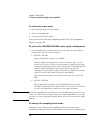
• “To select the state mode” on page 44
• “To select the 200 MHz/400 MHz state speed configuration” on page 44
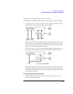
• “To change the sampling clock mode” on page 44
• “To set up the sampling clock” on page 46
State Mode Sampling
Position
In order for a state mode logic analyzer to accurately capture data from
a device under test, the logic analyzer's setup/hold time (window) must
fit within the device under test's data valid window.
Because the location of the data valid window relative to the bus clock
is different for different types of buses, the logic analyzer lets you
adjust the sampling position in order to accurately capture data on
high-speed buses (see “Understanding State Mode Sampling Positions”
on page 208).
When the device under test's data valid window is less than 2.5 ns
(roughly, for clock speeds >= 200 MHz), it's easiest to use eye finder
to locate the stable and transitioning regions of signals and to
automatically adjust sampling positions.
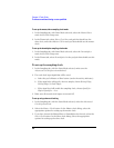
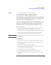
• “To automatically adjust sampling positions” on page 47
When the device under test's data valid window is greater than 2.5 ns
(roughly, for clock speeds < 200 MHz), it's easiest to adjust the
sampling position manually, without using the logic analyzer to locate
the stable and transitioning regions of signals.
• “To manually adjust sampling positions” on page 50


