


Calibration 77
CALibration:SAVE
Writes the present calibration constants into the EEPROM. This command does not have to be sent until all ranges and
modes have been calibrated. If the unit is turned off before CAL:SAVE is sent, the new calibration constants are lost
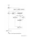
Calibration Flowcharts
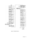
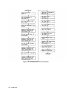
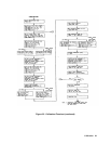
The flowchart in Figures 6-2 describes the calibration procedure. It corresponds to the example calibration program. The
flowchart indicates the appropriate statement that is used in the program example to accomplish each step. It also indicates
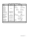
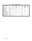
when to set the power supply to the appropriate voltage and current output. Refer to Table 6-2 for the variable values,
power supply settings, and current shunts associated with the model that you are calibrating.
Calibration mode is turned on at the beginning of the calibration procedure. Remember to save the calibration constants
after you have verified that they are within specifications. Do not turn calibration mode off until after you have saved the
new calibration constants - otherwise the new calibration constants will be lost.
Note When calibrating the high calibration point of the high current range and high current transient level, you
must wait about 30 seconds for the internal current shunt of the module to stabilize with the full current
applied before you execute the CAL:MEAS:HIGH command. Because the high current range
calibration causes the Electronic Load to heat up, you should also allow about 30 seconds time for the unit
to cool down to room temperature before continuing to calibrate any other modes or ranges.
One shortcut that is used in this calibration procedure is that the readback DAC is calibrated for current readback after the
high current range calibration, and calibrated for voltage readback after the voltage range calibration. This is because the
readback setups are the same as the setups for the high current and voltage ranges. Another shortcut is that the same values
are used to calibrate the main DAC as well as the readback DAC. You may wish to use different values to calibrate the
readback DAC to optimize accuracy.
It is not necessary to calibrate the current readback for the low current range or for reading back resistance values. This is
because the high current readback calibration takes care of the low current range. The resistance values that are readback
are calculated based on the voltage at the input terminals and the current through the internal current shunt resistor. If the
readback DAC has been calibrated for voltage and current readback, resistance readback will be accurate.
Note Remember to turn the unit off after you have saved the new calibration constants. When the unit is turned
on again, the new calibration constants are used to recalculate the software OP and OC limits. These
limits are not updated until power is cycled.
Example Program
The example program in this chapter is written in the Agilent BASIC Language. If you are using an HP Series 200/300
computer, simply type in the program and run it. If you are using a different computer or programming language, you will
have to modify the program before you can run it.
The program can be used to calibrate all Electronic Load models. You must specify the address of the Electronic Load that
you are calibrating as shown in line 10. (The program assumes address 705.) Line 20 specifies channel 1 which is the
channel number used by all Single Input Electronic Load models. You must make the variable assignments for the model
that you are calibrating in lines 40 through 90. Refer to table 6-2 for the values that apply to the model you are calibrating.
Do not change the last value (Flag) in lines 40, 50, 70, 80, and 90.
When the program is run, it will stop at appropriate places and prompt you to set the power supply according to Table 6-2,
enter your measured values into the computer, and verify that the values are within specifications.