


16 General Information
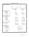
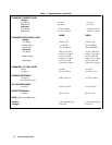
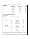
Table 1-2. Supplemental Characteristics (continued)
Voltage Slew Rate:
6060B (0 to 60V) 6063B (0 to 240V) Transition
Rate # Voltage Step Voltage Step Time*
1 1 V/ms 4 V/ms 8.0 ms
2 2.5 V/ms 10 V/ms 3.2 ms
3 5 V/ms 20 V/ms 1.6 ms
4 10 V/ms 40 V/ms 800
µ
s
5 25 V/ms 100 V/ms 320
µ
s
6 50 V/ms 200 V/ms 160
µ
s
7 0.1 V/
µ
s 0.4 V/
µ
s 100
µ
s
8 0.25 V/
µ
s 1 V/
µ
s 100
µ
s
9 0.5 V/
µ
s 2 V/
µ
s 100
µ
s
*Transition time is based on low capacitance current source.
Resistance Slew Rate
Low Range: Uses the value programmed for the voltage slew rate.
Middle and High Ranges: Uses the value programmed for the current slew rate.
TRANSIENT CURRENT OVERSHOOT (When programmed from 0A):
Model 6060B
Range Transient Current Level Current Slew Rate Overshoot*
60 A 6-60 A All slew rates 0
3 A I A/
µ
s to 5 A/
µ
s1%
3 A I A/ms to 0.5 A/
µ
s0
6 A 6 A All slew rates 0
3 A 0.25 A/
µ
s and 0.5 A/
µ
s1%
3 A 0.1 A/ms to 0.1 A
µ
s0
Model 6063B
Range Transient Current Level Current Slew Rate Overshoot*
10A 2-10 A All slew rates 0
0.5 A 0.17 A/
µ
s to 0.83 A/
µ
s5%
0.5 A 0.17 A/ms to 42 A/ms 0
1 A 0.83 A/
µ
s1%
1 A 0.17 A/ms to 0.17 A/µs0
1 A 0.5 A 83 A/ms 4%
0.5 A 17 A/s to 17 A/ms 0
1 A All slew rates 0
*All overshoot values assume a total inductance of 1 µH, or less, in the load leads connected to the D.U.T. For Model
6060B, overshoot may be higher during first five seconds of programming if the unit has been operating at full current.