Installation 45
Parallel Connections
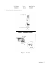
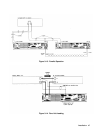
Figure 3-13 illustrates how Electronic Loads can be paralleled for increased power dissipation. Up to six Electronic Loads
can be directly paralleled in CC or CR mode. Units cannot be paralleled in CV mode.
Each Electronic Load will dissipate the power it has been programmed for. For example, if two Electronic Loads are
connected in parallel, with Electronic Load number 1 programmed for 10 A and module number 2 programmed for 20 A,
the total current drawn from the source is 30 A.
In Figure 3-13, all lead connections are terminated at the source. Each Electronic Load is connected to the source using
separate wires. Using the source as the current distribution point allows larger wires to be used for each Electronic Load
connection and also reduces the common impedance inherent in daisy-chained configurations.
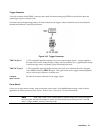
Figure 3-13 shows one method of triggering Electronic Loads that are connected in parallel. The TRIG OUT signal of
Electronic Load number 1 is connected to the TRIG IN input of Electronic Load number 2. Additional Electronic Loads
can be daisy chained to Electronic Load number 2 in the same manner. Once the new settings of the Electronic Loads have
been programmed, one trigger signal can be used to simultaneously set all of the Electronic Loads to their new settings.
Zero-Volt Loading Connections
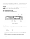
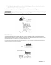
As shown in Figure 3-14, the Electronic Load can be connected in series with a voltage source or auxiliary power supply
greater than 3 V so that the Electronic Load can test devices at its full current capacity down to a zero-volt level. Remote
sensing is recommended for improved load regulation and when turning the short on.
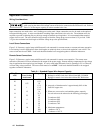
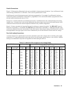
Table 3-2. Maximum Wire Lengths to Limit Voltage Drops
Wire Size
Resistivity
Maximum Length in Meters (Feet) to Limit
Voltage Drop to 0.5 V or Less
Cross Section
AWG Area in mm
2
Ω/kft Ω/km
5 A 10 A 20 A 30 A 40 A 50 A 60 A
22 16.15 (6) (3) (1.5) (1) (0.77) (0.62) (0.52)
0.5 40.1 2.5 1.2 0.6 0.4 0.31 0.25 0.21
20 10.16 (9.5) (4.5) (2) (1.5) (1.23) (0.98) (0.82)
0.75 26.7 3.7 1.9 0.9 0.6 0.47 0.37 0.31
18 6.388 (15.5) (7.5) (3.5) (2.5) (2.0) (1.57) (1.30)
1 20.0 5.0 2.5 1.3 0.8 0.63 0.50 0.42
16 4.018 (24.5) (12) (6) (4) (3.1) (2.49) (2.07)
1.5 13.7 7.3 3.6 1.8 1.2 0.91 0.73 0.61
14 2.526 (39.5) (19.5) (9.5) (6.5) (4.9) (3.46) (3.30)
2.5 8.21 12.2 6.1 3.0 2.0 1.52 1.22 1.01
12 1.589 (62.5) (31) (15.5) (10.5) (7.9) (6.29) (5.24)
4 5.09 19.6 9.8 4.9 3.3 2.46 1.96 1.64
10 0.9994 (100) (50) (25) (17) (12.5) (10.00) (8.34)
6 3.39 29 14.7 7.4 4.9 3.69 2.95 2.96
8 0.6285 (159) (79) (39.5) (27) (19.9) (15.91) (13.25)
10 1.95 51 25 12.8 8.5 6.41 5.13 4.27
6 0.3953 (252) (126) (63) (40) (31.6) (25.30) (21.07)
16 1.24 80 40 20 13.4 10.08 8.06 6.72
4 0.2486 (402) (201) (100) (68) (50.37) (40.23) (33.51)


