


28 Operation Overview
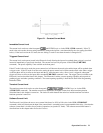
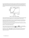
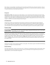
In cases where the transition from one setting to another is large, the actual transition time can be calculated by dividing the
voltage or current transition by the slew rate. The actual transition time is defined as the time required for the input to
change from 10% to 90% or from 90% to 10% of the programmed excursion. In cases where the transition from one setting
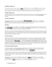
to another is small, the small signal bandwidth of the load limits the minimum transition time for all programmable slew
rates. Because of this limitation, the actual transition time is longer than the expected time based on the slew rate, as shown
in Figure 2-7.
Figure 2-7. Risetime Transition Limitation
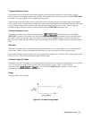
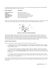
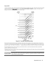
Therefore, both minimum transition time and slew rate must be considered when determining the actual transition time. This
is shown in Figure 2-8 for the twelve programmable slew rates in current mode operation. The actual transition time will be
either the total slew time (transition divided by slew rate), or the minimum transition time, whichever is longer.
In voltage mode, all minimum transition times are based on a low-capacitance current source. These transition times are
affected by capacitive loading of the inputs. For example, a capacitance of 2.2 microfarads increases the 85 microsecond
minimum transition time (shown in the specifications table) to 110 microseconds. Therefore, no graph is provided for
minimum transition time and slew rate in voltage mode operation.
In resistance mode, the low resistance range uses the slew rate that has been programmed for voltage mode. The middle
resistance range uses the slew rate that has been programmed for the high current range. The high resistance range uses the
slew rate that has been programmed for the low current range.
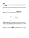
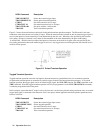
Input Current, Voltage, and Power Measurement
Each load’s input current, voltage, and power can be measured at the front panel (
key) or via the GPIB (MEAS
command). With local (front panel) control in effect, pressing
will continually step the display through voltage and
current input values, the computed power value, and various status conditions for the selected channel.
With remote control in effect, a load may be instructed to measure its dc input voltage, current, or power by sending the
appropriate query command (e.g. MEAS:CURR). The results will be read back when the load is addressed to talk.
Voltage and current measurements are performed with approximately 12-bit resolution of full scale ratings. Power is
computed from this information.