


44 Installation
Application Connections
Wiring Considerations
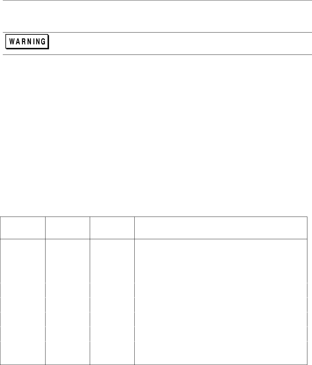
FIRE HAZARD To satisfy safety requirements, load wires must be heavy enough not to overheat
while carrying the short-circuit output current of the device connected to the Electronic Load. Refer to
Table 3-1 for the ampere capacity of various stranded wire sizes.
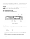
Input connections are made to the + and - binding posts on the panel. (Input connections can also be made to the optional
front panel binding posts). A major consideration in making input connections is the wire size. The minimum wire size
required to prevent overheating may not be large enough to maintain good regulation. It is recommended that stranded,
copper wires be used. The wires should be large enough to limit the voltage drop to no more than 0.5 V per lead. Table
3-2 gives the maximum load lead length to limit the voltage drop to the specified limit.
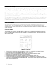
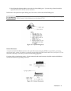
Local Sense Connections
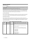
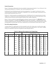
Figure 3-11 illustrates a typical setup with Electronic Load connected for constant current or constant resistance operation.
Local sensing is used in applications where lead lengths are relatively short, or where load regulation is not critical. The
sense switch must be set to LCL. Load leads should be bundled or tie-wrapped together to minimize inductance.
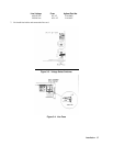
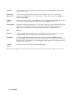
Remote Sense Connections
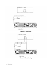
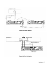
Figure 3-12 illustrates a typical setup with Electronic Load connected for remote sense operation. The remote sense
terminals of Electronic Load are connected to the output of the power supply. Remote sensing compensates for the voltage
drop in applications that require long lead lengths. It is only useful when Electronic Load is operating in CV or CR mode,
or when using voltage readback. The sense switch must be set to RMT. Load leads should be bundled or tie wrapped
together to minimize inductance.
Table 3-1. Stranded Copper Wire Ampere Capacity
Wire Size Ampacity Notes:
AWG Cross Section
Area in mm
2
1. Ratings for AWG-sized wires derived from MIL-W-5088B.
Ratings for metric-sized wires derived from IEC Publication
22 5.0 33-51.
20 8.33 .
0.75 10
18 15.4 2. Ampacity of aluminum wire is approximately 84% of that
1 13.5 listed for copper wire.
16 19.4
1.5 16 3. When two or more wires are bundled together, ampacity
14 31.2 for each wire must be reduced to the following percentages:
2.5 25
12 40 2 conductors 94%
4 32 3 conductors 89%
10 55 4 conductors 83%
6 40 5 conductors 76%
8 75
10 63 4. Maximum temperatures:
6 100
Ambient = 50° C
4 135
Conductor = 105° C