


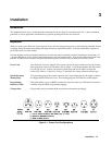
Installation 39
Power Test
Note The following checkout assumes that the Electronic Load is set to the factory defaults listed in Table 4-6.
Refer to Chapter 4 if you need to recall the factory default values.
Use a power supply with the voltage set to 10 V and the current limit set to 10 A to check the input circuits. The settings of
the power supply were only selected to agree with the following procedure. You can use different settings, but you must set
the Electronic Load accordingly.
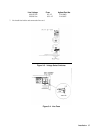
1. Connect the power supply to the Electronic Load input binding posts using heavy wires to minimize the
voltage drop in the wires.
2. Observe that the front panel of the Electronic Load displays the voltage that the power supply was set to
(10 V).
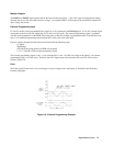
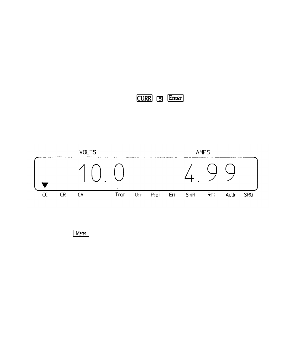
3. Depress the following front panel keys in the indicated order:
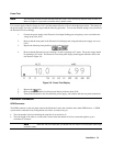
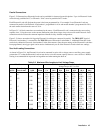
4. Observe that the Electronic Load is drawing 5 A and is operating in CC mode. The power supply should
be operating in CV mode. The Electronic Load front panel display should appear about the same as the
one shown in Figure 3-6.
Figure 3-6. Power Test Display
5. Depress the
key.
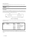
6. Observe that the Electronic Load front panel display indicates about 50 W.
7 Turn off the Electronic Load, disconnect the power supply, and continue with the rear panel connections.
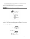
Controller Connection
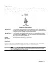
GPIB Connector
The GPIB connector on the rear panel connects the Electronic Load to the controller and to other GPIB devices. A GPIB
system can be connected in any configuration (star, linear, or both) as long as:
• The total number of devices including the controller is no more than 15.
• The total length of all cables is no more than 2 meters times the number of devices connected together, up to a
maximum of 20 meters.
Note IEEE Std. 488-1978 states that you should exercise caution if an individual cable length
exceeds 4 meters.