


9
Check the oil pump pressure. Standard
operating pressure is 100 PSIG.
After reaching steady state, take a
smoke test. If not indicating a trace, set
the combustion air controls to provide a
trace.
Typically, the CO
2
reading will range
from 11.5% to 13.5%.
After the air adjustments have been
completed, and the air shutter or air ad-
justment plate has been secured, re-
check the breech draft and take another
smoke test to ensure that the values
have not changed.
SMOKE TEST NOTE:
If oily or yellow smoke spots are found
on the smoke test filter paper, it is usu-
ally a sign of unburned fuel. This indi-
cates poor combustion. This type of
problem may be caused by excess draft,
excess air, or contaminated fuel. Do not
ignore this indicator.
STACK TEMPERATURE:
Stack temperature will vary depending
on fuel input, circulating air blower
speed, and burner set up, etc. In gen-
eral, stack temperature should typically
range between 380°F to 550°F, assum-
ing that the combustion air is approxi-
mately room temperature (65°F - 70°F).
In general, lower stack temperature indi-
cates greater efficiency; however, ex-
cessively low stack temperature can lead
to condensation forming in the chimney
and / or venting. Sulphur and similar
contaminants in the fuel oil will mix with
condensation to form acids. Acids and
resultant chemical salts will cause rapid
deterioration of the chimney and venting
components, and may attack the fur-
nace.
If the flue gases are below the range, it
may be necessary to slow down the
blower fan. If the flue gases are above
the range, the blower fan may require
speeding up. Stack temperature varies
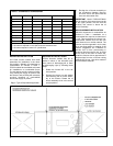
directly with the system temperature rise.
System temperature rise is the difference
between the furnace outlet temperature
and furnace inlet temperature as meas-
ured in the vicinity of the connection be-
tween the plenum take-offs and the trunk
ducts. Typical temperature rise values
range between 70°F and 85°F.
If the venting from the furnace to the
chimney is long, or exposed to cold am-
bient temperatures, it may be necessary
to use L-Vent as the vent connector to
reduce stack temperature loss to prevent
condensation. The venting should be
inspected annually to ensure that it is
intact.
FURNACE INSTALLATION
SET-UP
The furnace must be set up as the final
step in the installation.
A) The oil burner must be set up follow-
ing the procedures outlined above.
B) The furnace should operate within a
temperature rise of 85°F ±15°F. To de-
termine the temperature rise, measure
the supply air and return air tempera-
tures when the furnace has reached
steady state conditions. This is the point
at which the supply air temperature stops
increasing relative to the return air tem-
perature. The furnace may have to run
10 to 15 minutes to reach steady state
conditions. The measurements may be
made with duct thermometers or thermo-
couples used in conjunction with multi-
meters with temperature measurement
capabilities.
The return air should be measured at a
point where the thermometer will be well
within the air stream near the furnace
return air inlet. Actual location is not par-
ticularly critical; however, avoid locations
where the temperature readings could be
affected by humidifier bypass ducts, the
inside radius of elbows, etc.
The supply air temperature should be
measured at a point where the ther-
mometer will be well within the air stream
near the furnace supply air outlet. Usu-
ally, the side mid-point of the supply air
plenum take-off is ideal, providing it is
out of the line of sight to the heat ex-
changer. If the thermometer is within the
line of sight of the heat exchanger, the
supply air readings may be skewed by
radiant heat from the heat exchanger. If
the plenum take-off is unsuitable, the
supply air temperature may be measured
within the first 18 inches of the first seg-
ment of supply air trunk duct.
If the temperature rise is outside the rec-
ommended range, it may be adjusted on
direct drive equipped units by selecting
alternate circulation fan motor speeds,
on belt drive equipped units by adjusting
the variable speed motor pulley. If the
temperature rise is too high, speed the
fan up. If the temperature rise is too low,
slow the fan down.
C) Keep in mind that the stack tem-
perature varies directly with the tempera-
ture rise. The higher the temperature
rise, the higher the stack temperature will
be, resulting in lower efficiency. The
lower the temperature rise, the lower the
stack temperature will be, which, in some
cases, may allow condensation to form
in the chimney and other vent parts.
D) Test the high limit control to ensure
that it is operating correctly. For direct
drive equipped units, this may be done
by temporarily removing the circulator
fan heating wire or neutral wire. For belt
drive equipped units, temporarily remove
the fan belt. Turn of electrical power to
the furnace before working with the mo-
tor wires or fan belt. Be sure to protect
any removed wires from shorting out on
metal furnace parts. If the high limit test
is successful, shut off the electrical
power to the furnace, restore the proper
motor wiring. Finally, restore power to
the furnace.
E) Adjust the “Fan Off” setting on the
L6064A or L4064W fan limit controller. In
most cases, the “Fan Off” temperature
should be 90° to 100°F as indicated on
the thermometer used to measure the
supply air temperature. Once the “Fan
Off” setting has been established, set the
“Fan On” setting. In most cases, the “Fan
On” setting should be approximately
30°F higher than the Fan Off” setting.
NOTE: The L4064W fan/limit controller
has an auxiliary “fan on” function that
activates when the thermostat is calling
for heat. The controller is designed to
start the circulating fan in 20 to 30 sec-
onds. Adjust the “fan on” setting on the
controller dial 30°F higher than the “fan
off” setting even though the circulating
fan will normally be started by the auxil-
iary “fan on” function.
F) Operate the furnace through a
minimum of three full heating cycles.
During this time, check for fuel oil leaks,
gross air leakage from the supply air
ductwork, unusual noises originating
anywhere within the heating system
which may cause some concern or an-
noyance to the home owner, etc.
G) Be sure that the homeowner is
familiar with the furnace. The
homeowner should be aware of the
location of electrical circuit breaker or
fuse, the location of any electrical
switches controlling the furnace, the
location of the oil tank shut-off valve and
how to operate the valve. The home-
owner should be informed where the oil
tank gauge is located and how to read it.
It would be beneficial to review safety
issues with the home owner, such as the
danger of storing combustibles too close
to the furnace, hanging anything on the
furnace vent pipe, and especially the
dangers of indiscriminately pressing the
burner reset button.