


29
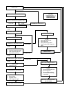
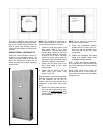
The above diagrams show typical ap-
proaches to framing the rough size open-
ing for the P*DHX series furnaces. Be
sure to follow local building code re-
quirements with respect to framing modi-
fications.
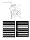
P3DHX12F08001 VESTIBULE KIT
When the P3DHX12F08001 furnace is
installed in the downflow position, the
Part No. 1VP1280 Vestibule Kit may be
used. The vestibule kit encloses the oil
burner assembly and provides a pleasing
exterior finish.
NOTE: The vestibule kit should be in-
stalled before installation of the electrical
wiring, venting and fuel line or lines.
1. Fasten the right hand panel to the
base panel using 2 10-¾ sheet
metal screws. The right hand panel
has the large opening in the lower
end to accommodate a combustion
air pipe to the oil burner. The base
panel has screw holes along the
rear edge, which will later be used to
fasten the vestibule to the furnace.
2. Fasten the left hand panel to the
base panel using 2 10-¾ sheet
metal screws.
3. Fasten the top panel to the two
sides using 10-¾ sheet metal
screws, 3 per side.
Note the pattern of small and large holes
along the base panel and two side pan-
els. The vestibule unit will use the
screws in the front of the furnace which
correspond to the small holes noted
above.
4. Remove the sheet metal screws in
the furnace front panel which corre-
spond to the small holes only
along
the rear edge of the vestibule base
and side panels.
NOTE: Do not remove all screws from
the front panel of the furnace.
5. Place the assembled vestibule
against the front panel of the fur-
nace, and align the vestibule screw
holes with the furnace front panel
screw holes.
6. Fasten the vestibule into place
using the screws which were
removed from the furnace.
HINT: To help with fastener alignment,
do not tighten any of the screws all the
way in until each screw has been started
2 or 3 turns.
NOTE: Extra sheet metal screws are
provided with this kit in case screws re-
moved from the furnace are accidentally
dropped or lost.