


4
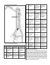
SUSPENDED INSTALLATION
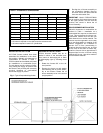
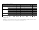
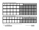
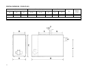
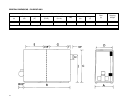
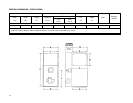
Refer to Figure 1. Maintain clearances to
combustibles as outlined in Table 1. The
furnace may be suspended by field fabri-
cating a cradle of angle iron and
threaded rod. Secure the furnace with 2
inch minimum slotted angle or equiva-
lent, as shown in Figure 1. The furnace
must be supported in such a way as to
not allow twisting or sagging of the cabi-
net. Position the supports so as to not
interfere with accessing the burner and
blower compartments. Suggestion; as a
measure to prevent fuel oil from accumu-
lating in locations other than the fire pot,
as could be the case in the event of noz-
zle drip, install the furnace with an ap-
proximate 2 degree slope from the oil
burner casing towards the fire pot.
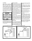
AIR CONDITIONING
If the furnace is used in conjunction with
air conditioning, the furnace shall be
installed in parallel with or upstream from
the evaporator coil to avoid condensation
in the heat exchanger. In a parallel
installation, the dampers or air controlling
means must prevent chilled air from en-
tering the furnace. If the dampers are
manually operated, there must be a
means of control to prevent the operation
of either system unless the dampers are
in the full heat or full cool position. The
air heated by the furnace shall not pass
through a refrigeration unit unless the
unit is specifically approved for such
service.
Generally, a six-inch clearance between
the air conditioning evaporator coil and
the heat exchanger will provide adequate
airflow through the evaporator coil.
The blower speed must be checked and
adjusted to compensate for the pressure
drop caused by the evaporator coil. Re-
fer to Appendix B for recommended wir-
ing and electrical connections of the air
conditioning controls.
COMBUSTION AIR
When a furnace is installed in the full
basement of a typical frame or brick
house, infiltration is normally adequate to
provide air for combustion and draft op-
eration. If the furnace is installed in a
closet or utility room, two (2) ventilation
openings must be provided connecting to
a well ventilated space (full basement,
living room or other room opening
thereto, but not a bedroom or bathroom).
One opening shall be located 6" from the
top and bottom of the enclosure at the
front of the furnace. For furnaces located
in buildings of unusually tight construc-
tion, such as those with high quality
weather stripping, caulking, windows and
doors, or storm sashed windows, or
where basement windows are well
sealed, a permanent opening communi-
cating with a well ventilated attic or with
the outdoors shall be provided, using a
duct if necessary. Size all of the open-
ings and associated ductwork by the
standards provided in the latest Oil In-
stallation Code editions; NFPA 31 in the
United States, CAN/CSA B139 in Can-
ada. Take all fuel burning appliances in
the area into consideration when calcu-
lating combustion and ventilation air re-
quirements.
The Model CAS-2B-90E Furnace Boot
manufactured by Field Controls, Inc. may
be used with the furnace to obtain com-
bustion air directly from outdoors. Use of
this device does not alter the need for
ventilation air; however, it does provide a
good direct source of combustion air and
is connected directly to the oil burner.
CHIMNEY VENTING
The chimney must be sized correctly and
be in good repair. If the chimney is over-
sized, there is a high risk of the flue
gases condensing resulting in damage to
the chimney and other venting parts.
This problem may be corrected by the
use of an appropriately sized chimney
liner.
If the chimney serves the
P3DHX12F08001 furnace only, the vent
should be sized at 4-inch minimum, 5-
inch maximum. If the chimney serves the
P2DHX16F12001 or P2LBX16F14501
furnace only, the vent should be sized at
4-inch minimum, 6-inch maximum. If the
chimney serves the P4LBX20F19001
furnace only, the vent should be sized at
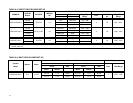
5-inch minimum, 7-inch maximum. The
data provided in Table 3 is based on
dedicated venting. If the furnace is to be
co-vented with other appliances, refer to
NFPA 211, Standard for Chimneys, Fire-
places, Vents, and Solid Fuel-Burning
Appliances, NFPA 31, Standard for the
Installation of Oil Burning Equipment or
CAN/CSA B139, Installation Code For
Oil Burning Equipment for correct sizing
information.
NOTE: This furnace is approved for
use with L-Vent.
NOTE: Maximum temperature for L-
Vent is 575°F (300°C).
IMPORTANT: The chimney must be
capable of providing sufficient draft at all
times for the safe removal of the prod-
ucts of combustion.
The chimney should be tested under
“winter” conditions; doors and windows
closed, all other fossil fuel burning appli-
ances on, clothes dryer on, bathroom
fans on, etc. If the chimney cannot over-
come the competition for air, it will be
necessary to access the reason for it,
and take corrective action. If the chimney
is found to be sized correctly and in good
repair, it will probably be necessary to re-
evaluate the availability of combustion
and ventilation air, and take corrective
action.
The flue pipe should be as short as pos-
sible with horizontal pipes sloping up-
ward toward the chimney at a rate of
one-quarter inch to the foot. The flue
pipe should not be smaller in cross sec-
tional area than the flue collar on the
furnace. The flue pipe may be reduced in
size to fit a smaller diameter chimney
with the use of a tapered reducer fitting
at the chimney inlet. The flue pipe should
connect to the chimney such that the flue
pipe extends into, and terminates flush
with the inside surface of the chimney
liner. Seal the joint between the pipe and
the lining. The chimney outlet should be
at least two feet above the highest point
of a peaked roof. All unused chimney
openings should be closed. Chimneys
must conform to local, provincial or state
codes, or in the absence of local regula-
tions, to the requirements of the National
Building Code.
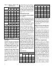
See Figure 2 and Table 2 for common
chimney problems and their remedies.
THE FURNACE MUST BE CON-
NECTED TO A FLUE HAVING SUFFI-
CIENT DRAFT AT ALL TIMES TO EN-
SURE SAFE AND PROPER OPERA-
TION OF THE APPLIANCE.
The flue pipe must not be routed through
concealed space, because it must be
visually checked for signs of deteriora-
tion during the annual inspection and
servicing. The flue pipe must not pass
through any floor or ceiling, but may
pass through a wall where suitable fire
protection provisions have been in-
stalled. In the United States, refer to the
latest edition of NFPA 31 for regulations
governing the installation of oil burning
equipment. In Canada, refer to the latest
edition of CAN/CSA B139 for rules gov-
erning the installation of oil burning
equipment.