


28
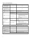
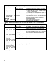
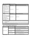
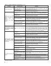
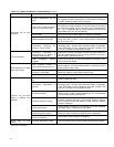
Table C-3: System and General Troubleshooting
continued
Problem Possible Cause Remedy
Airflow blocked or dirty air fil-
ter.
Clean or replace air filter.
Supply air temperature
too hot.
Insufficient airflow.
Check all dampers. Open closed dampers including registers in
unused rooms. Check system temperature rise. If temperature
rise is too high, speed up blower fan.
Excess airflow.
Check system temperature rise. Slow down blower fan if neces-
sary.
Supply air temperature
too cool.
Excessive duct losses.
Check supply air ductwork. Seal leaky joints and seams. Insu-
late ductwork if necessary.
Fan control "fan on" setting too
low.
Increase differential between fan control "fan off" and "fan on"
settings. (L4064B, L6064A fan / limit controls only, no adjust-
ments available for L4064W fan / limit control). Register air de-
flectors may help.
Supply air temperature
too cool during first mo-
ments of furnace cycle.
Excessive duct losses.
Check supply air ductwork. Seal leaky joints and seams. Insu-
late ductwork if necessary.
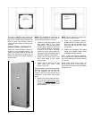
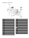
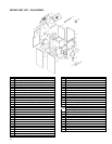
P4LBX20F19001 ASSEMBLY
NOTES
The P4LBX20F19001 oil-fired furnace is
shipped in two pieces; the furnace sec-
tion and the blower section. These two
sections must be assembled together at
the installation site.
1. Remove the crating and packaging
materials from each section. Re-
move the flue pipe flange gasket
packed with the furnace section.
The flue pipe gasket will be lying
loose on the floor of the furnace sec-
tion.
2. Remove the shipping brace from the
furnace section flue pipe flange and
cabinet. Remove and save all of the
screws from the flue pipe flange,
and the ten screws from the rear
edges of the furnace section cabi-
net, (5 per side). The screws will be
re-used.
3. Place the furnace section and
blower section in close proximity.
Route the wiring harness from the
base of the furnace section through
the plastic grommet in the blower
section blower division panel.
4. Position and align the flue pipe
flange gasket between the furnace
section and blower section flue pipe
flanges, and hold it in place with a
pair of awls or similar tool.
5. Begin fastening the flue pipe flanges
together from inside the blower sec-
tion to the furnace section with the
six ¼-20 x ¾ inch screws saved
from the removal of the shipping
brace. Start each screw carefully so
as not to damage the flue pipe
flange gasket. After all six screws
have been started, and proper gas-
ket alignment has been confirmed,
tighten all six screws evenly.
6. Align the screw holes in the blower
section blower division panel with
the screw holes in the furnace sec-
tion cabinet rear edge, from which
the ten screws were removed. The
screws are started from the inside of
the blower section to the furnace
section. Tighten all ten screws
evenly.
7. In a similar manner, start four of the
extra screws removed and saved
from the furnace section flue pipe
flange into the screw holes along the
top of the two furnace sections.
8. Remove the blower motor electric
wiring cover plate. Connect the
black lead from the wiring harness
to motor terminal L1, the white lead
to motor terminal L2, and the green
lead to the motor casing ground
terminal. Position the wires in the
motor casing indentations and re-
install the blower motor electric wir-
ing cover plate.
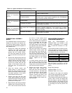
P3DHX SERIES DOWNFLOW
CONFIGURATION NOTES
When the P3DHX12F08001 or
P2DHX16F12001 are installed in the
downflow configuration on a wooden
floor, it should be mounted on a sub-
base.
The sub-base provides a means of main-
taining the supply air plenum clearance
to combustibles, and a means of mating
the supply air plenum to the furnace.
Model Sub-base
P3DHX12F08001 1CB1312
P2DHX16F12001 1CB0316
If the furnace is to be installed on a wood
floor over joists on 12 inch or 16 inch
centers, framing modifications are nec-
essary.
Rough Size Openings:
P3DHX12F08001: 21” x 21”.
P2DHX16F12001: 22½” x 22½”.
The edges of the rough size opening
must be well supported by the joist fram-
ing to take the weight of the furnace.
The sub-base may support the supply air
plenum. Fold a ¾ inch, 90° flange, then
drop the supply air plenum through the
sub-base opening. The flanges will rest
on the sub-base, and the furnace placed
on the flange will lock the plenum into
place.