


3
DOWN-FLOW INSTALLATION
All P*DHX furnace models have been
assembled for installation in the down-
flow position. Maintain all clearances to
combustibles as outlined in Table 1.
P*DHX models have available sub-bases
for installations on combustible floors.
The sub-bases provide a means of effec-
tively mating the supply air plenum with
the furnace, and providing the necessary
one-inch clearance to combustibles
around the supply air plenum.
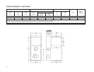
HORIZONTAL INSTALLATION
P*DHX furnaces models may be in-
stalled in either of the horizontal posi-
tions; warm air discharging left or warm
air-discharging right by following these
steps:
1. Rotate the furnace 90° to the de-
sired position.
2. Remove the three nut and washer
sets fastening the oil burner assem-
bly to the furnace. Rotate the oil
burner assembly to be in the normal
upright position.
3. Re-align the oil burner assembly to
the combustion chamber (fire-pot),
and then secure into place with the
three nut and washer sets.
IMPORTANT: Model P3DHX12F08001
has an auxiliary limit control that must be
in the upper position. Be sure that the
auxiliary limit control is above the oil
burner assembly.
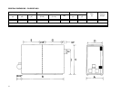
NON-SUSPENDED INSTALLATION
Maintain clearances to combustibles as
outlined in Table 1. Installation on a
combustible floor requires a clearance of
1 inch. This can be done by using a non-
combustible material such as one inch
thick channel iron or similar material. The
furnace must be supported in such a way
as to not allow twisting or sagging of the
cabinet. Suggestion; as a measure to
prevent fuel oil from accumulating in
locations other than the fire pot, as could
be the case in the event of nozzle drip,
install the furnace with an approximate 2
degree slope from the oil burner casing
towards the fire pot. Use shims made of
noncombustible material.
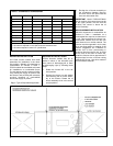
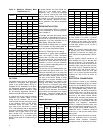
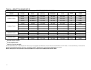
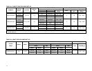
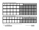
Table 1: Clearance to Combustibles
Furnace P2LBX P3DHX12F08001 P2DHX16F12001
Location Upflow Downflow Horizontal Downflow Horizontal
Top 3 in. 0 in. 6 in. 0 in. 3 in.
Bottom 0 in. 0 in. 1 in. 1 in. 1 in.
S/A
Plenum
0 in. 1 in. 1 in. 1 in. 3 in.
Rear 1 in.
1
1 in. 1 in. 1 in. 1 in
Sides 6 in.
2
1 in. 1 in. 1 in. 0 in.
Front 24 in. 6 in.
1
24 in. 16 in.
1
24 in.
Flue Pipe 9 in.
3
9 in.
3
9 in.
3
9 in.
3
9 in.
3
Enclosure Standard Closet - - - Closet Alcove
1
24 inches is required for servicing.
2
18 inches is required on one side as service access to rear.
3
18 inches required in some U.S. jurisdictions
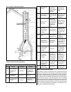
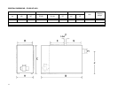
Fig. 1: Typical Suspended Application