


7
ers and humidifiers may be included on
the furnace circuit. Although a suitably
located circuit breaker can be used as a
service switch, a separate service switch
is advisable. The service switch is nec-
essary if reaching the circuit breaker
involves becoming close to the furnace,
or if the furnace is located between the
circuit breaker and the means of entry to
the furnace room. The furnace switch
(service switch) should be clearly
marked, installed in an easily accessible
area between the furnace and furnace
room entry, and be located in such a
manner to reduce the likelihood that it
would be mistaken as a light switch or
similar device.
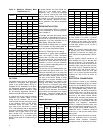
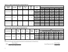
The power requirements for all models:
120 VAC, 1 ∅, 60 Hz.
Maximum fuse size for the P*DHX mod-
els and P2LBX16F14501 model: 15
amps. Maximum fuse size for the
P4LBX20F19001 model: 20 amps.
Accessories requiring 120 VAC power
sources such as electronic air cleaners
and humidifier transformers may be
powered from the furnace circuit. Do not
use the direct drive motor connections as
a power source, since there is a high risk
of damaging the accessories by expo-
sure to high voltage from the auto-
generating windings of the direct drive
motor.
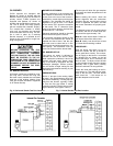
Thermostat wiring connections and air
conditioning contactor low voltage con-
nections are shown in the wiring dia-
grams. Some micro-electronic thermo-
stats require additional controls and wir-
ing. Refer to the thermostat manufac-
turer's instructions.
The thermostat should be located ap-
proximately 5 feet above the floor, on an
inside wall where there is good natural
air circulation, and where the thermostat
will be exposed to average room tem-
peratures. Avoid locations where the
thermostat will be exposed to cold drafts,
heat from nearby lamps and appliances,
exposure to sunlight, heat from inside
wall stacks, etc.
Normal heat anticipator setting: for the
P*LBX models is 0.1 A. Normal heat
anticipator setting: for the P*DHX models
is 0.4 A .For more precise adjustment,
the heat anticipator may be adjusted to
the amperage draw of the heating control
circuit as measured between the "R" and
"W" terminals of the thermostat. To re-
duce the risk of damaging the heat an-
ticipator, do not measure circuit without
first removing one of the two wires first.
To determine the heating circuit amper-
age draw:
1. Disconnect one of the “R” or “W”
wires from the thermostat terminal.
2. Connect an ammeter between the
wire and the thermostat terminal to
which it was attached.
3. Note the amperage reading when
the heating contacts are closed.
(System switch must be on “
HEAT
” if
so equipped.
4. Re-connect the thermostat wire. If
the thermostat is serving a combina-
tion heating and air conditioning sys-
tem, pay particular attention to
polarity.
5. When the thermostat is reconnected
and re-plumbed, adjust the heat an-
ticipator setting to match the ob-
served amperage reading.
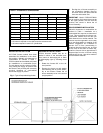
CIRCULATING AIR BLOWER
Both P*DHX and the P2LBX16F14501
furnace models are equipped with a di-
rect drive blower system. Direct drive
blower speed adjustments are not nor-
mally required in properly sized extended
plenum duct systems. The motor RPM
and air CFM delivery will vary automati-
cally to accommodate conditions within
the usual range of external static pres-
sures typical of residential duct systems.
Under-sized duct systems may require a
higher blower speed to obtain a reason-
able system temperature rise. Some
older duct systems were not designed to
provide static pressure. They typically
feature special reducing fittings at each
branch run and lack block ends on the
trunk ducts. These systems may require
modification to provide some resistance
to the airflow to prevent over- amping of
the direct drive blower motor. Selecting a
lower blower speed may correct this
problem.
Direct drive blower speeds are adjusted
by changing the "hot" wires to the motor
winding connections. Please refer to
wiring diagram in Appendix B or the wir-
ing diagram label affixed to the furnace.
THE NEUTRAL WIRE (normally the
white wire) IS NEVER MOVED TO AD-
JUST THE BLOWER SPEED.
DO NOT CONNECT POWER LEADS
BETWEEN MOTOR SPEEDS. THE
NEUTRAL WIRE MUST ALWAYS BE
CONNECTED TO THE MOTOR'S DES-
IGNATED NEUTRAL TERMINAL.
It is possible and acceptable to use a
single blower speed for both heating and
cooling modes. The simplest method to
connect the wiring from both modes is to
use a "piggy-back connector" accommo-
dating both wires on a single motor tap.
It is also acceptable to connect the se-
lected motor speed with a pigtail joined
to both heating and cooling speed wires
with a wire nut. As a safety precaution
against accidental disconnection of the
wires by vibration, it is advisable to se-
cure the wire nut and wires with a few
wraps of electricians tape.
If the joining of the blower speed wiring
is done in the furnace junction box, tape
off both ends of the unused wire.
The P4LBX20F19001 furnace model is
equipped with a belt drive blower sys-
tem. The blower speed (RPM) and resul-
tant airflow can be varied by adjusting
the variable speed motor pulley.
DISCONNECT THE POWER SUPPLY
TO THE FURNACE BEFORE OPEN-
ING THE BLOWER ACCESS DOOR
TO SERVICE THE AIR FILTER, FAN
AND MOTOR. FAILURE TO SHUT OFF
POWER COULD ALLOW THE
BLOWER TO START UNEXPECT-
EDLY, CREATING A RISK OF DEATH
OR PERSONAL INJURY.
Do not use the blower speed wires as
a source of power to accessories as
electronic air cleaners and humidifier
transformers. The unused motor taps
auto-generate sufficiently high volt-
ages to damage accessory equip-
ment.
Do not start the burner or blower fan
unless the blower access door is se-
curely in place.