


6
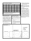
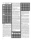
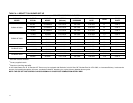
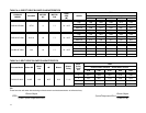
Table 3: Minimum Chimney Base
Temperatures (°F)
Chimney Height (ft.)
Nozzle
11 20 28 36
Chimney Thermal Resistance < R6
0.50 300 400 535 725
0.65 275 340 430 535
0.75 260 320 380 475
0.85 250 300 355 430
1.00 245 300 355 430
1.10 245 290 345 400
1.20 240 275 320 365
1.50 240 275 320 365
1.65 235 270 300 345
Chimney Height (ft.)
Nozzle
11 20 28 36
Chimney Thermal Resistance > R6
0.50 185 200 220 250
0.65 175 185 205 220
0.75 175 185 195 210
0.85 165 185 195 205
1.00 165 185 195 205
1.10 165 185 195 205
1.20 165 180 190 200
1.50 165 175 185 195
1.65 165 175 180 190
< -
less than
, > -
greater than
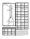
OIL TANK
Oil storage tanks must be selected and
installed in compliance with applicable
codes; in the United States, NFPA 31,
Standard for the Installation of Oil Burn-
ing Equipment, Chapter 2. and in Can-
ada, CAN/CSA-B139, Installation Code
for Oil Burning Equipment, Section 6.
Observe all local codes and by-laws.
In general, the oil tank must be properly
supported and remain stable in both
empty and full condition. The oil tank
must be fitted with vent and supply pipes
to the outdoors. Refer to the above-
mentioned codes for sizing. The vent
pipe must be no less than 1¼ inches
I.P.S., and terminate with an appropriate
vent cap in a location where it will not be
blocked. The fill pipe must be no less
than 2 inches I.P.S., and terminate with
an appropriate cap in a location where
debris will not enter the fill pipe during oil
delivery.
If located indoors, the tank should nor-
mally be in the lowest level, (cellar,
basement, etc.). It must be equipped
with a shut-off valve at the tank outlet
used for the oil supply. The oil tank must
be located as to not block the furnace /
room exit pathway. Observe all clear-
ances specified in the above-mentioned
codes.
PIPING INSTALLATION
In the United States, NFPA 31, Standard
for the Installation of Oil Burning Equip-
ment, Chapter 2.
In Canada, the entire fuel system should
be installed in accordance with the re-
quirements of CAN/CSA B139, and local
regulations. Use only approved fuel oil
tanks piping, fittings and oil filters.
Ensure that all fittings used in a copper
oil line system are high quality flare fit-
tings. Do not use compression fittings.
Do not use Teflon tape on any fittings.
Pressurized or gravity feed installations
must not exceed 3 PSIG. Pressures
greater than 10 PSIG may cause dam-
age to the shaft seal. If the height of the
oil stored in a tank above the oil burner
exceeds 11½ feet, it may be necessary
to use a pressure-regulating device ap-
proved for this purpose.
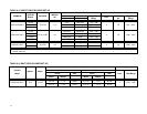
The furnace may be installed with a one-
pipe system with gravity feed or lift. The
maximum allowable lift on a single line
system is 8 feet. Lift should be measured
from the bottom (outlet) of the tank, to
the inlet of the burner. Sizing a single
line system is complex because of the
difficulty estimating the pressure drop
through each fitting, bend and compo-
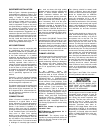
nent in the line. In general, keep single
line systems short as possible. 2-stage
oil pumps are not available for either the
P*HMX or P*LBX furnaces. The following
chart shows the allowable line lengths
(horizontal + vertical) for single and two-
line oil piping systems. All distances are
in feet.
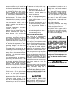
Table 4: Oil Lines
Copper Tubing Oil Line Length (Feet)
Single-Pipe Two-Pipe
Lift
(Feet)
⅜”
OD
½” OD
⅜”
OD
½” OD
0 53 100 68 100
1 49 100 65 100
2 45 100 63 100
3 41 100 60 100
4 37 100 58 100
Continue
5 33 100 55 100
6 29 100 53 100
7 25 99 50 100
8 21 83 48 100
9 17 68 45 100
10 13 52 42 100
12 - - - - - - 37 100
14 - - - - - - 32 100
16 - - - - - - 27 100
18 - - - - - - 22 88
In retrofit applications, where an existing
oil line system is in place, a vacuum
check will help determine the efficacy of
the existing oil line system The vacuum
in a system should not exceed 6” Hg. for
a single pipe system, nor 12” Hg. for a
two-pipe system.
NOTE: The oil burner requires the use of
a bypass plug when converting from
single-pipe to two-pipe oil piping sys-
tems. See burner manufacturer’s instruc-
tions.
All fuel systems should include an oil
filter between the fuel oil storage tank
and the oil burner. For best results, in-
stall the oil filter as close to the burner as
possible. When using an indoor oil tank,
the oil filter may be installed at the tank
downstream from the shut-off valve. If
firing the furnace under the 0.65 gph
rate, a 7 to 10 micron line filter should be
installed as close to the oil burner as
possible.
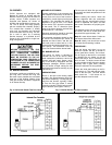
ELECTRICAL CONNECTIONS
The furnace is listed by the Canadian
Standards Association (CSA). All models
except for the P4LBX20F19001 are fac-
tory wired and require minimal field wir-
ing. The P4LBX20F19001 model is pre-
wired except for the wiring connections
to the blower motor. The wires from the
furnace section are routed through the
grommet in the blower section blower
division panel, and then connected to the
blower motor. In the United States, the
wiring must be in accordance with the
National Fire Protection Association
NFPA-70, National Electrical Code, and
with local codes and regulations. In Can-
ada, all field wiring should conform to
CAN/CSA C22.1 Canadian Electrical
Code, Part 1, and by local codes, where
they prevail.
The furnace should be wired to a sepa-
rate and dedicated circuit in the main
electrical panel; however, accessory
equipment such as electronic air clean-