


8
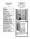
OIL BURNER
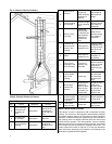
P*LBX furnaces are equipped with
Beckett AF Series oil burners with the
Beckett CleanCut pump and R7184B oil
primary control. P*DHX furnaces are
equipped with Beckett AF Series oil
burners with the R8184N oil primary con-
trol. The oil burner must align properly
with the cerafelt fiber chamber (firepot).
The cerafelt fiber chamber is initially
quite soft, but hardens and becomes
quite brittle after the first firing. The fire-
pot is held in place by a retaining
bracket; however, it is possible for the
firepot to shift if subjected to rough han-
dling during transit.
BEFORE OPERATING THE FUR-
NACE CHECK BURNER ALIGNMENT
WITH COMBUSTION CHAMBER.
THE END CONE OF THE AIR TUBE
MUST BE CENTRED TO THE AC-
COMODATING RING PROVIDED IN
THE DESIGN OF THE COMBUSTION
CHAMBER. ADJUST ALIGNMENT AS
NECESSARY BEFORE THE FIRST
FIRING.
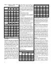
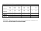
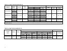
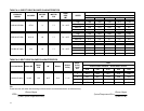
OIL BURNER NOZZLES
All furnace models are certified for multi-
ple firing rates. Choose the firing rate
that most closely matches the calculated
heat loss of the building. Models, firing
rates and nozzles are listed in Appendix
A: AF Burner Set-Up.
BURNER ELECTRODES
Correct positioning of the electrode tips
with respect to each other, to the fuel oil
nozzle, and to the rest of the burners is
essential for smooth light ups and proper
operation. The electrode tips should be
adjusted to a gap of 5/32”, 1/16” ahead
of the nozzle, 5/16” above the centerline
of the nozzle. The “Z” dimension (front
edge of the burner head to the front face
of the nozzle is 1-1/8 inches.
Electrode positioning should be checked
before the first firing of the furnace.
The electrode porcelains should be free
of cracks, the electrode tips should be
tapered and free of burrs, and the con-
tact rods must be clean and be in firm
contact with the ignition transformer con-
tact springs. The electrodes must not
come into contact with the burner head.
OIL BURNER SET-UP
The burner air supply is adjusted to
maintain the fuel to air ratio to obtain
ideal combustion conditions. A lack of air
causes "soft" and "sooty" flames, result-
ing in soot build-up throughout the heat
exchanger passages. Excess combus-
tion air causes a bright roaring fire and
high stack temperatures resulting in poor
fuel efficiency.
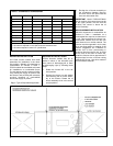
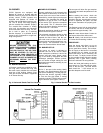
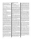
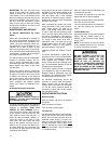
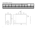
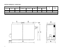
PREPARATIONS:
Drill a ¼” test port in the venting, ideally
at least 2 flue pipe diameters away from
the furnace breeching, if venting horizon-
tally from the furnace, (typically P*LBX)
or from the flue pipe elbow if venting
vertically (typically P*DHX) before reach-
ing the furnace. (see Figures 4 and 5).
The test port will allow flue gas samples
to be taken and stack temperatures to be
measured.
Before starting the burner, check the
burner alignment with the combustion
chamber (fire pot), check that the correct
nozzle is tightened into place, and that
the burner electrodes are properly posi-
tioned.
The Beckett burner bulk air band should
be closed, and the air shutter initial set-
ting should be approximately 7.00.
Note A: Locate hole at least 6 inches on
the furnace side of the draft control.
Note B: Ideally, hole should be at least
12 inches from breeching or elbow.
PROCEDURE:
Start the burner and allow it to run at
least ten minutes. Set the air shutter to
give a good flame visually. The combus-
tion air supply to the burner is controlled
by adjusting the air shutter on the left
side of the burner, and, if necessary, the
bulk air band. To adjust, loosen the bolt
on the movable shutter. Move the shutter
gradually until a good flame (visually)
has been achieved. Re-snug the bolt.
Check the initial draft setting as the fur-
nace warms up. The draft may be meas-
ured at the test port. The final breech
draft should be - 0.02 inches w.c. to
provide adequate over-fire draft.
Fig. 4: Horizontal Smoke Test Port Location Fig. 5: Vertical Smoke Test Port Location