


Page 48
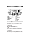
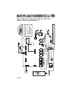
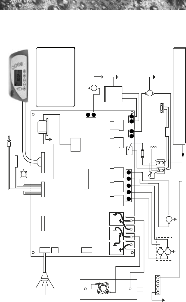
16.0 Electrical Wiring Diagram (60 Hz)
(Marin, Capri, and Altamar)
SYSTEM CONTROL
PANEL
SENSORS 800 LCD PANEL
TB1
TB3
TB1
240 VAC, 24A / 40A / 48A, 1-Phase, 60 Hz
USE COPPER CONDUCTORS ONLY
Wire size must be appropriate per NEC and/or Local Codes
TB4
J4
J8
J2
K8
K6K5K4
K7
TB6
TB2
J1
Z1
J6 J7
J3
OPTIONS
FLOW SWITCH
HI - LIMIT / FREEZE SENSOR
TRANSFORMER
T1
BLOWER
CIRCULATION
PUMP
Blk
Wht
RED
Wht
Wht
Wht
Blk
Red
BLK
Blk
30A, 250V, SC-30
F1
PUMP 2
PUMP 1
HI
HI
LO
GRN
2
1
SPA LIGHT
TB5
TB3
K13
20
21
1
1 2 1 2
3 5
8 10
BB
TEMPERATURE
SENSOR
To Heater
Relays
HEATER
5.5 kW, 240 VAC
Wht
Blk
UV or CD
Ozonator
(Optional)
STEREO
(Optional)
This device complies with part 15 of
the FCC rules. Operation is subject to
the following two conditions:
1. This device may not cause harmful
interference.
2. This device must accept any
interference received including
interference that may cause
undesired operation.
Power Supply
K1 K2 K3