


ASSEMBLY
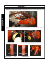
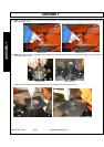
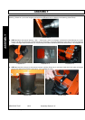
Connect the “windrow-former” to the “shoe” with a set hexagon oval head screw M10x35 and 1 self-locking nut M10 for rear
fastening (Picture 23.1) and a set hexagon oval head screw M10x30 and a nut M10 for front fastening (Picture 23.2).
Picture 23.3
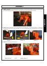
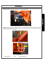
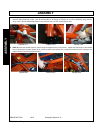
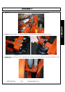
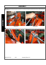
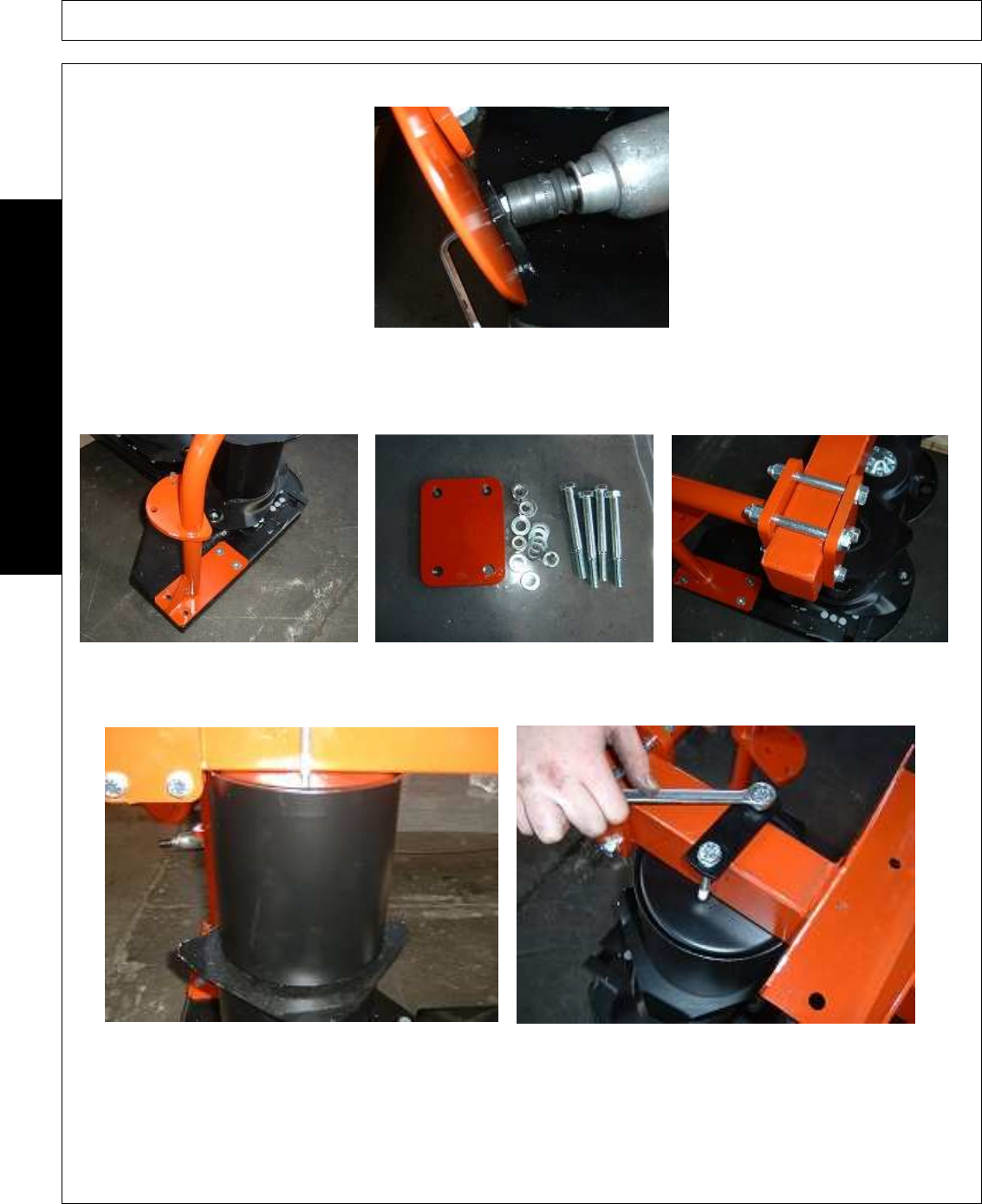
STEP 24. Mount the external bearing - “bow” – (Picture 24.1) with 4 set hexagon countersunk screws M12x40 and 4 self-
locking nuts M12 (see Picture 24.2 for attaching to the mowing bar). As regards attachment to the upper rod use the plate with
4 holes, 4 hexagon head screws M12x110, 4 self-locking nuts M12 and 8 flat washers M12 (Picture 24.3) – Do not tighten too
much.
Picture 24.1 Picture 24.2 Picture 24.3
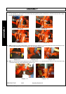
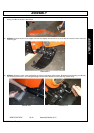
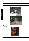
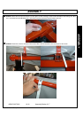
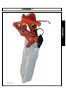
STEP 25. Insert the conveyor on the external conveyor cylinder (Picture 25.1) and fasten it with the 2 hole- plate, 2 hexagon
head screws M10x100 and 2 flat washers Ø10 – Do not tighten too much.
Picture 25.1 Picture 25.2
ASSEMBLY
AGM 52-62-72-82
10/10
Assembly Section 3-14
© 2010 Alamo Group Inc.