


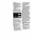
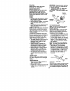
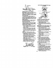
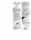
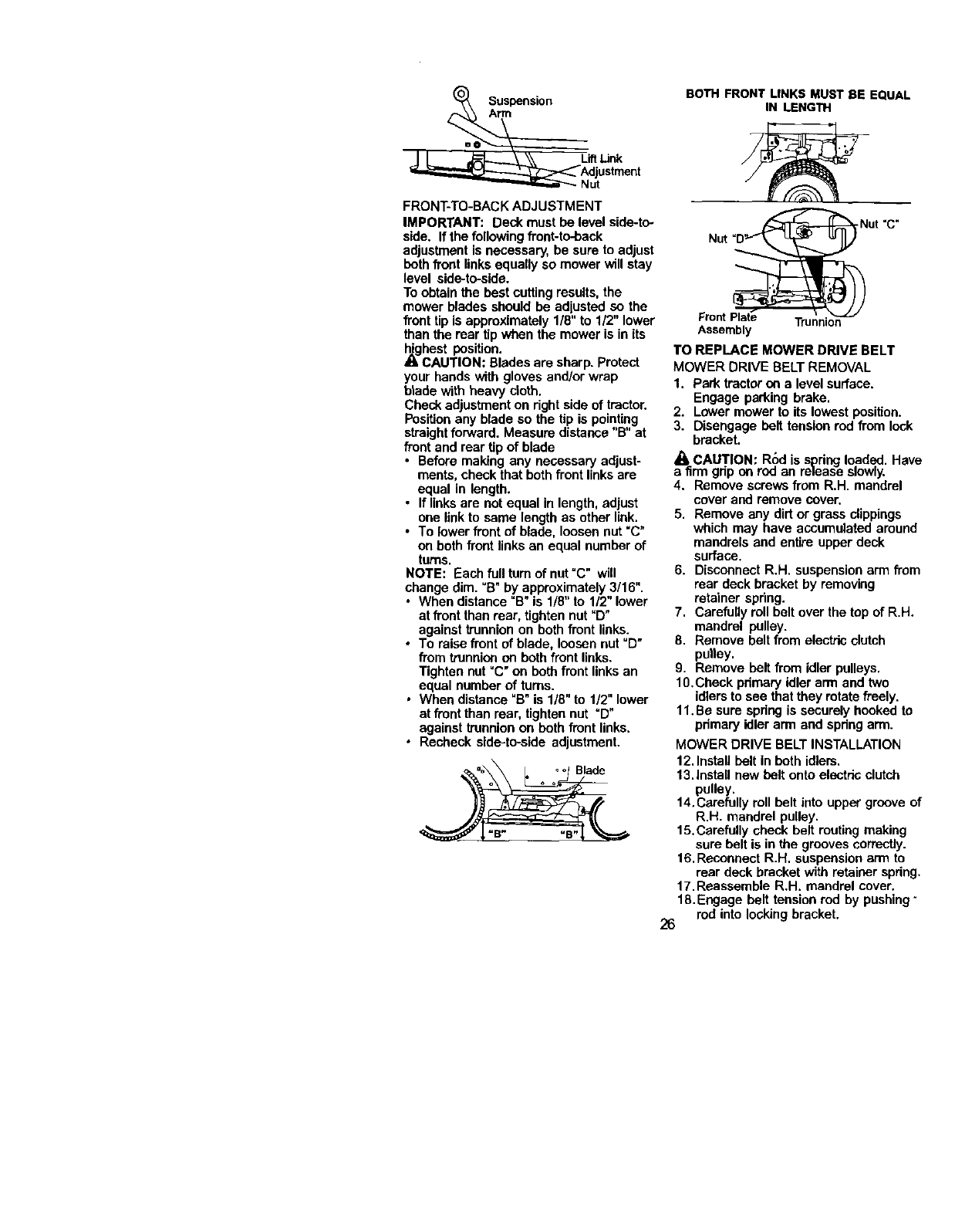
SuspensionA_
_i,i_ Adjustment
_-""_ Nut
FRONT-TO-BACK ADJUSTMENT
IMPORTANT: Deck must be level side-to-
side. If the following front-to-back
adjustment isnecessary, be sure to adjust
beth frontlinks equally somower willstay
level side-to-side.
Toobtain the best cuttingresults,the
mower blades should be adjusted so the
front tip isapproximately 1/8" to 1/2" lower
than the rear tipwhen the mower is inits
highest position.
CAUTION: Bladesare sharp. Protect
your hands with gloves and/or wrap
blade with heavy cloth.
Check adjustment on right side of tractor.
Positionany blade so the tip is pointing
straightforNard. Measure distance"13"at
front and rear tip of blade
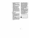
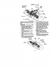
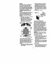
• Before making any necessary adjust-
ments, check thatboth front linksare
equal in length.
• If linksare not equal inlength, adjust
one linkto same length as other link.
• To lower front of blade, loosen nut "C"
on both frontlinks an equal number of
turns.
NOTE: Each full turnof nut "C" will
change dim. "B" by approximately 3/16".
• When distance "B" is 1/8" to 1/2" lower
at front than rear, tighten nut "D"
against trunnionon bothfront links.
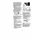
• To raise front ofblade, loosen nut"D"
from trunnion on both front links.
Tighten nut =C"on both front links an
equal number of turns.
• When distance "B" is 1/8" to 1/2" lower
at front than rear, tighten nut "D"
against trunnion on beth front links.
• Recheck side-to-side adjustment.
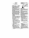
BOTH FRONT LINKS MUST BE EQUAL
IN LENGTH
Nut "C"
Trunnion
Assembly
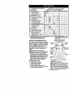
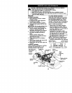
TO REPLACE MOWER DRIVE BELT
MOWER DRIVE BELT REMOVAL
1. Park tractoron a level surface.
Engage parking brake.
2. Lower mower to itslowest position.
3. Disengage belt tensionrod from lock
bracket.
• 1=CAUTION; R6d isspring loaded. Have
a firm gdp on rod an release slowly.
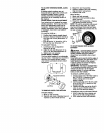
4. Remove screws from R.H. mandrel
cover and remove cover.
5. Remove any dirt or grass clippings
which may have accumulated around
mandrels and entire upperdeck
surface.
6. Disconnect R.H. suspensionarm from
rear deck bracket by removing
retainer spring.
7. Carefully rollbelt over the top of R.H.
mandrel pulley.
8. Remove belt from electricclutch
pulley.
9. Remove belt from idler pulleys.
10.Check pdmary idlerarm and two
idlersto see that theyrotate freely.
11. Be sure springis securely hooked to
primary idlerarm and spdng arm.
MOWER DRIVE BELT INSTALLATION
12.Install belt in both idlers.
13.Install new belt ontoelectric clutch
pulley.
14.Carefully roll belt into upper groove of
R.H. mandrel pulley.
15.Carefully check belt routingmaking
sure beltis in the groovescorrectly.
16.Reconnect R.H. suspensionarm to
rear deck bracket with retainer spdng.
17. Reassemble R.H. mandrel cover.
18.Engage belt tensionred by pushing"
rod into locking bracket.
26