


9
• You will reach correct adjustment when there is
minimal slack in the cable but it is not tight. Hold the
flats on the ferrule with pliers and tighten the jam
nut against the ferrule.
CAUTION: Cables will become loose if you do not
tighten the jam nut.
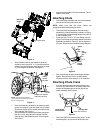
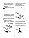
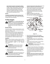
Attaching Shift Rod
• Place the shift lever in the sixth (6) speed.
• Place the bent end of the shift rod into the hole in the
shift arm assembly. See Figure 10 . Secure with 5/16
flat washer and hairpin clip from group D of the
hardware pack.
• Thread ferrule (included in group C) from the right
side onto the other end of the shift rod till it lines up
with the upper hole in the shift lever (beneath the
handle panel). While aligning the ferrule, push
down on the shift rod and the shift arm assembly
as far as it will go.
NOTE: You may have to pull the shift lever out of the
sixth speed position and move it towards the fifth speed
position until the ferrule slides into the hole without
force.
• Once the ferrule slides into the hole, turn it
counter-clockwise one more full turn and insert it
in the hole in the shift lever. For proper positioning
of the ferrule and the associated hardware, see
Figure 10 .
Figure 10
• Secure the ferrule to the shift lever with another 5/
16 flat washer and hairpin clip from group C of the
hardware pack. See Figure 10 .
• Check for correct adjustment of the shift rod, as
instructed in the Adjustment section, before
operating the snow thrower.
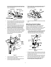
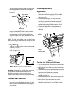
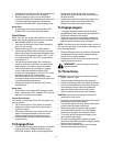
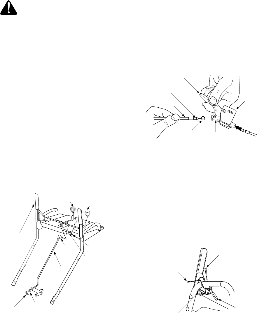
Attaching Turn Triggers
• Check and make sure that the right hand trigger
cable is routed in front of the traction drive cable.
• Feed the trigger cable up through the outer side of
the slot in the handle panel. Do not feed the cable
through the same side of the slot as the Z fitting.
• Place the cable barrel fitting into the hole in the
trigger. You can find the triggers and associated
hardware in group H of the hardware pack. See
Figure 11 .
Figure 11
• Pull on the cable and rotate it around the bottom of
the trigger, with the inner cable in the slot, until the
cable end can be pushed into the trigger housing
and snapped tight. See Figure 11 .
NOTE: When the cable is installed correctly, you
should not be able to pull the cable out of the trigger
housing.
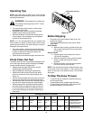
• Place the right turn trigger in position underneath
the right handle. Secure with screw and weld nut
from group G of the hardware pack. See Figure 5.
You will need a phillips screwdriver for tightening
the screw. Repeat on the left side.
Figure 12
WARNING: There must not be any tension
on either clutch cable with the drive or auger
clutch grip in the disengaged (up) position.
These clutches are a safety feature. Do not
override their function.
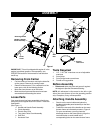
Traction
Drive
Clutch
Ferrule
Hairpin
Clip
Flat
Washer
Clip
Hairpin
Chute
Distance
Control
Shift
Rod
Shift Arm
Assembly
Flat
Washer
Shift
Lever
Barrel
Fitting
Trigger
Housing
Trigger
Assembly
Cable snaps in at
this end
Cable
Inner Cable
Slot
Secure with screw
Weld Nut
Slot
Trigger
Turn