


24
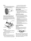
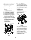
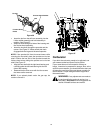
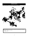
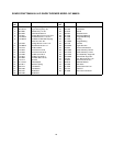
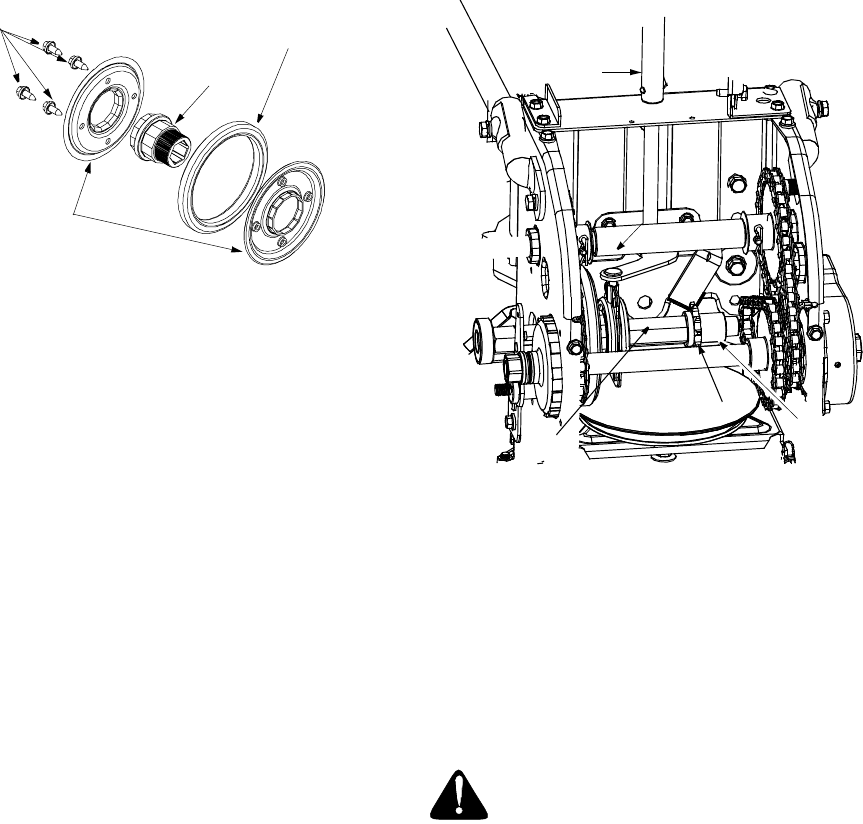
Figure 36
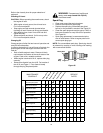
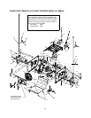
• Insert the pin from the shift arm assembly into the
friction wheel assembly and hold assembly in
position. See Figure 37.
• Slide hex shaft through left side of the housing and
the friction wheel assembly.
• Insert the hex shaft through the sprocket and the
spacer. See Figure 37. Make certain that chain
engages both the large and the small sprocket.
NOTE: If the sprocket fell from the snow thrower while
removing the hex shaft, place the sprocket on the hex
shaft. Position the hex hub of the sprocket toward the
friction wheel when sliding the sprocket on to the hex
shaft. See Figure 37.
• Align the hex shaft with the right hand bearing and
carefully guide the left hand bearing into the left
side of the housing.
• Reassemble the drive cover with the four screws
that were earlier removed.
NOTE: If you placed plastic under the gas cap, be
certain to remove it.
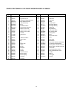
Figure 37
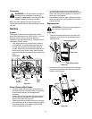
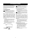
Carburetor
If you think the carburetor needs to be adjusted, see
your nearest authorized Sears Service Outlet.
If your snow thrower is left unused for 30 days or
longer, it needs to be prepared for storage. Also, at the
end of the snow season, you should follow the same set
of instructions and store the snow thrower properly for
the off-season. Proper storage ensures longer life of
the snow thrower.
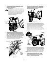
Friction Wheel Rubber
Screws
Friction Wheel
Hub
Plates
WARNING: If any adjustments are made to
the engine while the engine is running (e.g.
carburetor), keep clear of all moving parts. Be
careful of heated surfaces and muffler.
Sprocket
Spacer
Hex
Shaft
Shift Arm
Pin