


PowerLogic ION7550 / ION7650 Installation Guide
© 2007 Schneider Electric. All rights reserved. 9
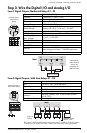
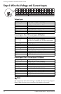
Step 3: Wire the Digital I/O and Analog I/O
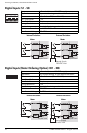
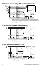
Form C Digital Outputs: Mechanical Relays R1 - R3
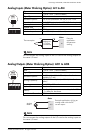
Form A Digital Outputs: Solid State Relays D1 - D4
Type Form C (R1, R2, R3)
Contacts K (common), Y (NO), Z (NC)
Wire Use wiring that is appropriate for the application
Connector Ring or split ring connector
Voltage Rating 250 VAC / 30 VDC
Rated Load @
Rated Voltage
Resistive: 10 A (AC/DC)
Inductive (PF=0.4): 7.5 A (AC) / 5 A (DC)
Max. Voltage 380 VAC / 125 VDC between K and NO/NC
MOV Protection 300 V max. between NO and NC
Max. Load @
Max. Voltage
3 A (AC) / 0.2 A (DC)
Turn-On Time 15 ms max.
Isolation 5,000 VAC for 60 s
Turn-Off Time 5 ms max.
Lifetime
No load = 10,000,000 operations
Rated voltage and load = 100,000 operations
Update time ½ cycle or 1 s
R
11
R
12
R
13
R
21
R12
R11
R13
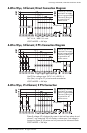
Internal Form C
Mechanical
Relay
External Supply
Alarm Lamp
NCNO
Load
Meter
K
Mechanical
relays should
always be
protected by
external fuses
Type Form A (D1, D2, D3, D4)
Wire
1.3 to 0.1 mm
2
(16 to 28 AWG)
Signal Type Continuous or pulse
Max. Load Voltage 30 VDC
Max. Load Current 80 mA per channel
Isolation
Optically isolated; max. 5,000 V RMS isolation
(UL-E91231)
Scan Time ½ cycle or 1 s
DIGITAL OUTPUTS
D3
-
+
D2
-
+
D4
-
+
D1
-
+
1.8 Wh
+
_
D1
Internal Form A
Solid State Relay
+
+
_
D3
_
D2
+
_ _
+
_
+
_
+
_
D1
+
D4 output is factory-configured to pulse once every 1.8 Wh for Class 20 meters,
or once every 0.18 Wh for Class 2 meters (for calibration testing purposes).
Meter
External
Relays
External Supply
30VDC max