


PowerLogic ION7550 / ION7650 Installation Guide
12 © 2007 Schneider Electric. All rights reserved.
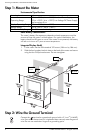
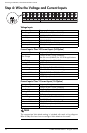
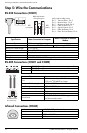
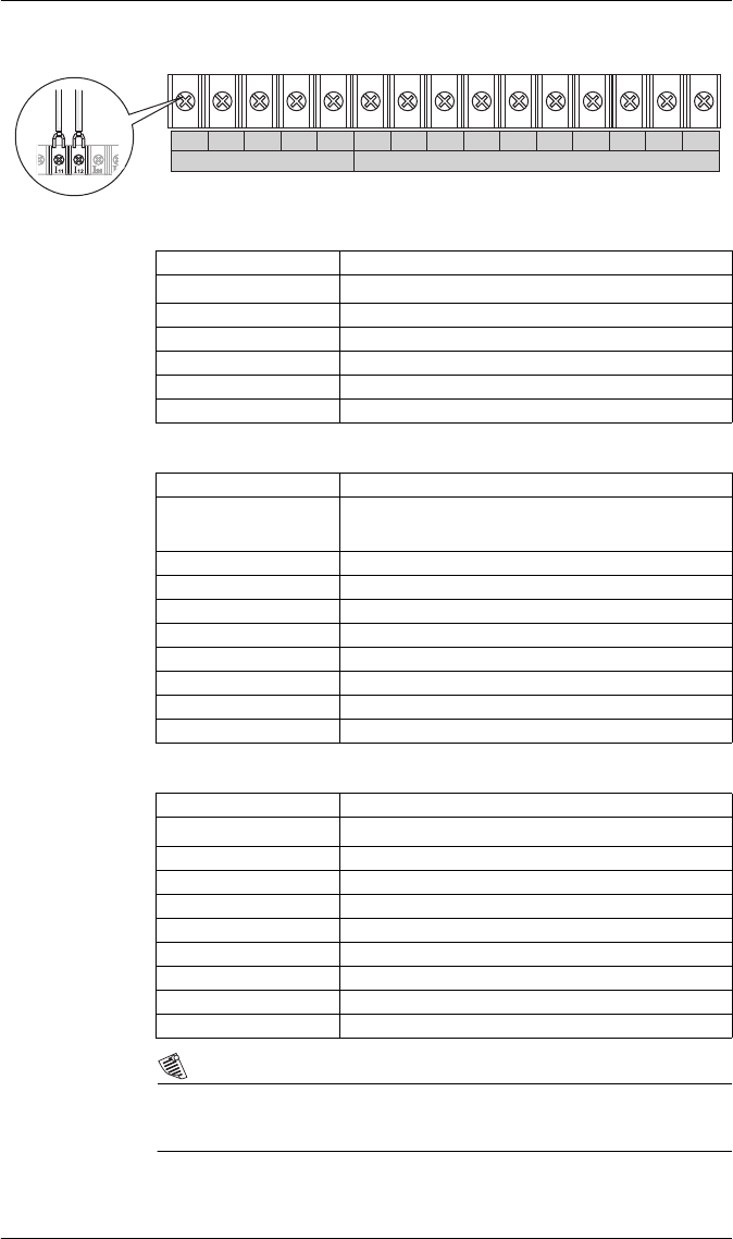
Step 4: Wire the Voltage and Current Inputs
Voltage Inputs
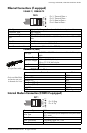
Current Inputs: Class 20 Current Inputs (5A Option)
Current Inputs: Class 2 Current Inputs (1A Option)
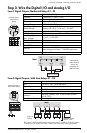
NOTE
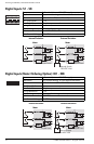
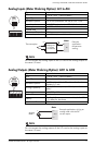
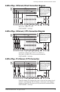
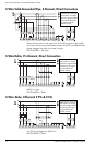
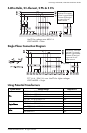
The appropriate Volts Mode setting is included with each wiring diagram.
Refer to Step 8 to learn how to configure Volts Mode on the meter.
3~ VOLTAGE INPUTS 3~ CURRENT INPUTS
V
3
V
4
V
ref
I
11
I
12
I
21
I
22
I
31
I
32
I
41
I
42
I
51
V
1
V
2
I
52
Connector Type Ring or split ring connector
Wire Gauge
3.3 to 2.1 mm
2
(12 to 14 AWG)
Rated Inputs 347 V L-N RMS /600 V L-L RMS
Fault Capture 1200 V L-N peak
Overload 1500 VAC RMS continuous
Dielectric Withstand 2500 VAC RMS at 60 Hz for 60 s
Input Impedance 5 MΩ/phase (phase - Vref)
Connector Type Ring or split ring connector
Wire Gauge
5.3 to 3.3 mm
2
(10 to 12 AWG):
Use 8.4 mm
2
(8 AWG) for 10-20 A applications
Input Rating 5 A, 10 A, and/or 20 A RMS
Starting Current 0.005 A RMS
Fault Capture 70 A peak
Max. Voltage 600 V RMS (CAT III IEC61010-1)
Overload 500 A RMS for 1 s, non-recurring
Dielectric Withstand 2500 VAC RMS at 60 Hz for 60 s
Burden 0.05 VA per phase (at 5 A)
Impedance 0.002 Ω per phase
Connector Type Ring or split ring connector
Wire Gauge
5.3 to 3.3 mm
2
(10 to 12 AWG)
Input Rating 1 A, 2 A, 5 A, and/or 10 A RMS
Starting Current 0.001 A RMS
Fault Capture 17.5 A peak
Max. Voltage 600 V RMS (CAT III IEC61010-1)
Overload 50 A RMS for 1s, non-recurring
Dielectric Withstand 2500 VAC RMS at 60 Hz for 60 s
Burden 0.015 VA per phase (at 1 A)
Impedance 0.015 Ω per phase