


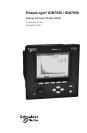

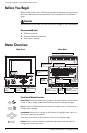
PowerLogic ION7550 / ION7650 Installation Guide
© 2007 Schneider Electric. All rights reserved. 3
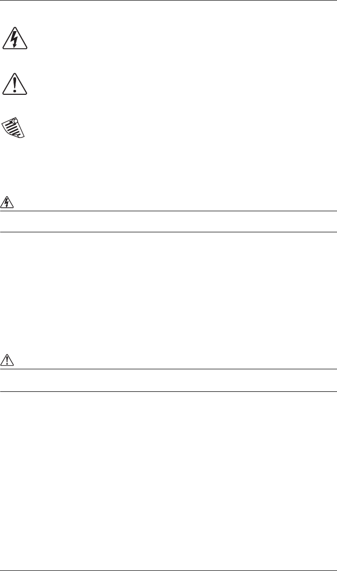
Danger
This symbol indicates the presence of dangerous voltage within and outside the product enclosure
that may constitute a risk of electric shock, serious injury or death to persons if proper precautions
are not followed.
Caution
This symbol alerts the user to the presence of hazards that may cause minor or moderate injury to
persons, damage to property or damage to the device itself, if proper precautions are not followed.
Note
This symbol directs the user’s attention to important installation, operating and maintenance
instructions.
Installation Considerations
Installation and maintenance of the PowerLogic ION7550 / ION7650 meter should only be performed by qualified,
competent personnel that have appropriate training and experience with high voltage and current devices. The meter
must be installed in accordance with all local and national electrical codes.
DANGER
Failure to observe the following instructions may result in severe injury or death.
During normal operation of the ION7550 / ION7650 meter, hazardous voltages are present on its termi-
nal strips, and throughout the connected potential transformer (PT), current transformer (CT), digital (sta-
tus) input, control power and external I/O circuits. PT and CT secondary circuits are capable of generating
lethal voltages and currents with their primary circuit energized. Follow standard safety precautions while
performing any installation or service work (i.e. removing PT fuses, shorting CT secondaries, etc.).
The terminal strips on the meter base should not be user-accessible after installation.
Do not use digital output devices for primary protection functions. These include applications where the
devices perform energy limiting functions or provide protection of people from injury. Do not use the
ION7550 / ION7650 in situations where failure of the devices can cause injury or death, or cause suffi-
cient energy to be released that can start a fire. The meter can be used for secondary protection functions.
Do not HIPOT/Dielectric test the digital (status) inputs, digital outputs, or communications terminals. Refer
to the label on the ION7550 / ION7650 meter for the maximum voltage level the device can
withstand.
CAUTION
Observe the following instructions, or permanent damage to the meter may occur.
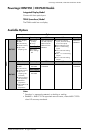
The ION7550 / ION7650 meter offers a range of hardware options that affect input ratings. The
ION7550 / ION7650 meter’s serial number label lists all equipped options. Applying current levels incom-
patible with the current inputs will permanently damage the meter. This document provides installation
instructions applicable to each hardware option.
The ION7550 / ION7650 meter’s chassis ground must be properly connected to the switchgear earth
ground for the noise and surge protection circuitry to function correctly. Failure to do so will void the
warranty.
Terminal screw torque: Barrier-type (current, voltage, and relay terminal screws: 1.35 Nm (1.00 ft-lbf)
max. Captured-wire type (
digital inputs/outputs, communications, power supply: 0.90 Nm
(0.66 ft.lbf) max.
FCC Notice
This equipment has been tested and found to comply with the limits for a Class A digital device, pursuant to Part 15
of the FCC Rules. These limits are designed to provide reasonable protection against harmful interference when the
equipment is operated in a commercial environment.