


PowerLogic ION7550 / ION7650 Installation Guide
16 © 2007 Schneider Electric. All rights reserved.
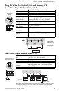
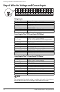
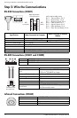
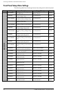
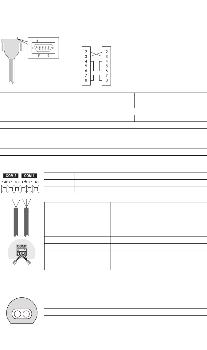
Step 5: Wire the Communications
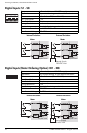
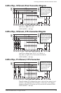
RS-232 Connections (COM1)
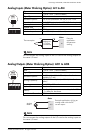
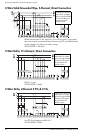
RS-485 Connections (COM1 and COM2)
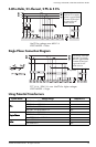
Infrared Connections (COM4)
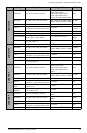
Null modem
cable pinout
Pin 3 - Transmit Data - Pin 2
Pin 2 - Receive Data - Pin 3
Pin 7 - Reque
st to Send- Pin 8
Pin 8 - Clear to Send- Pin 7
Pin 5 - Signal Ground- Pin 5
Pin 6 - Data Se
t Ready- Pin 4
Pin 4 - Data Terminal Ready- Pin 6
DB9 Null Modem
Wiring Diagram
DTE
(computer)
DTE
(meter)
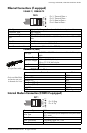
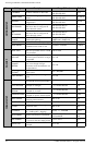
Specification Meter Connected to Computer
Meter Connected to External
Modem
Connector Type DB9 female end for mating with male connector on the meter
Wire Null modem RS-232 cable Straight-through RS-232 cable
Maximum Cable Length
15.2 m (50 ft)
Data Rate 300 – 115,200 bps
Isolation Optical
Duplex Full
Compliance ANSI/IEEE C37.90.1-2002 surge withstand and fast transient tests
SH RS-485 Shield (electrically connected to chassis ground)
– RS-485 Data Minus
+ RS-485 Data Plus
Connector Type Captured wire
Wire
Shielded twisted pair RS-485 cable,
0.33 mm
2
(22 AWG) or larger
Maximum Cable Length 1219 m (4000 ft) total for entire bus
Data Rate 300 – 115,200 bps
Maximum Devices (per bus) 32
Isolation Optical
Duplex Half
Compliance
ANSI/IEEE C37.90.1-2002 surge withstand
and fast transient tests
Connect SH at
one end only
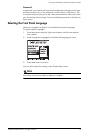
Interface ANSI C12.18 Type II optical port
Location Front of meter
Data Rate 1,200 – 19,200 bps
Duplex Half