


PowerLogic ION7550 / ION7650 Installation Guide
18 © 2007 Schneider Electric. All rights reserved.
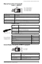
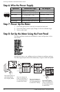
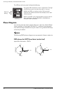
Step 6: Wire the Power Supply
Step 7: Power Up the Meter
1. Ensure the ground wire is securely connected on both ends.
2. Ensure the meter’s power supply voltage is within the allowed range.
3. Power up the meter.
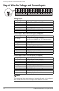
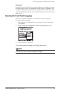
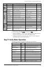
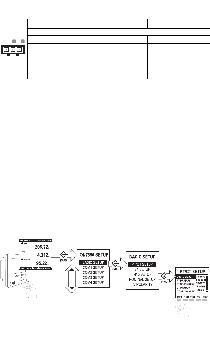
Step 8: Set Up the Meter Using the Front Panel
The following Setup screens are available for meter configuration via the
front panel:
Use the
PROG/SELECT, ESC, softkeys and arrow buttons to configure settings.
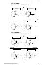
The following example shows Volts Mode setup using the meter front panel.
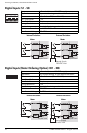
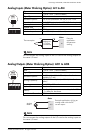
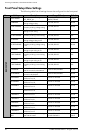
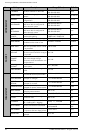
Specification Standard Power Supply Low Voltage DC
Type Captured wire connector
Wire
3.3-2.1 mm
2
(12-14 AWG) 2.1-0.8 mm
2
(14-18 AWG)
Rated Inputs
85-240 VAC ±10%
(47-63 Hz),
or 110-300 VDC ±10%
20-60 VDC ±10%
Dielectric Withstand 2500 VAC RMS at 60 Hz for 60s
Burden 35 VA max. (15 VA typical) 18 W max. (12 W typical)
Ride-through 100 ms (6 cycles at 60 Hz) min. None
G
N
_
L
+
BASIC SETUP
COM1 SETUP
COM2 SETUP
COM3 SETUP
COM4 SETUP
NETWORK SETUP
PQ SETUP
FORMAT SETUP
DISPLAY SETUP
TIME SETUP
SECURITY SETUP
METER RESETS
Press PROG/SELECT to
enter Setup Mode
from Display Mode.
Use arrow buttons to
move up and down in
list. Press PROG/SELECT
to select Basic Setup.
Use arrow buttons to
move up and down in
list. Press PROG/SELECT
to select PT/CT Setup.
Press Mode softkey.
Use arrow buttons to
move up and down in
list. Press PROG/SELECT
to select Delta.
Press
Press
Press
Press
Press
Press