


PowerLogic ION7550 / ION7650 Installation Guide
24 © 2007 Schneider Electric. All rights reserved.
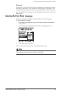
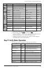
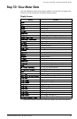
The LEDs on the front panel indicate the following:
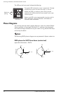
Phasor Diagrams
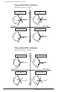
You can also view the meter’s phasor diagram in real time. Use the Phasor
Viewer available in PowerLogic ION Setup v2.1 and later (free download
from the PowerLogic website) to verify your meter’s wiring. See the ION Setup
online help for details.
NOTE
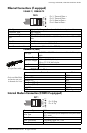
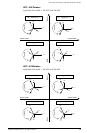
The following DELTA phasor diagrams are represented in System mode view.
DELTA phasors for UNITY Power Factor (resistive load)
Applicable Volts Mode = DELTA
Top (green) LED indicates the meter is operational. The light
should always remain on when the meter is in service.
Middle (red) LED is a watt-hour pulser. During normal
operations this LED should blink intermittently as the meter
measures power.
Bottom (red) LED is user programmable. It can be used for
Alarm notification. See the
ION7550 / ION7650 User
Guide
for more information.
Watt-hour
pulsing
Front Panel
IA
IC
IB
VAB
VBC
VCA
IA
IC
IB
VAB
VBC
VCA
ABC Rotation
ACB Rotation