


PowerLogic ION7550 / ION7650 Installation Guide
© 2007 Schneider Electric. All rights reserved. 23
1
A baud rate of 300 bps is only intended for paging applications.
2
Serial number = PA-0302B222-01, Unit ID = 2222
3
Default IP ADDRESS = 172.16.xxx.xxx, where the last two bytes (decimal)
match the last two bytes of the meter’s MAC address (hex).
4
NOMINAL VOLTAGE must be set to your system’s nominal voltage to
activate the meter’s power quality features.
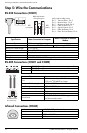
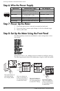
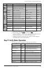
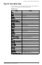
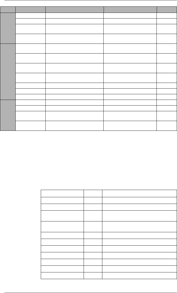
Step 9: Verify Meter Operation
The LEDs on the back of the meter flash during communications.
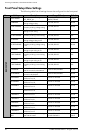
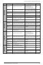
DISPLAY
SETUP
UPDATE RATE Sets when the display updates 1 to 6 (seconds) 1
CONTRAST Higher numbers are sharper 0 to 9 7
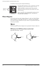
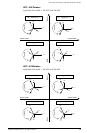
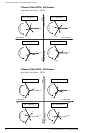
DELTA VECTORS
Specifies how vector diagrams are
displayed when in Delta mode
System or Instrument System
LANGUAGE
Specifies the language used on the
meter’s front panel
English, Spanish, French,
Russian
English
TIME SETUP
TZ OFFSET
Sets the time zone of the meter’s
location, relative to UTC
- 12:00 to +13:00 +00:00
DST OFFSET
Sets the daylight savings time offset
of the meter’s location
-3:00 to +3:00 +00:00
SYNC SOURCE
Sets the port to receive time
synchronization signals
Ethernet, COM1, COM2,
COM3, COM4
COM1
SYNC TYPE
Specifies whether time sync signals
are received in local time or UTC
Local Time or UTC UTC
CLOCK SOURCE Specifies time sync source Internal, Line Freq or COMM Line Freq
LOCAL DATE Sets the local date Same as Date Format setting
LOCAL TIME Sets the local time
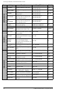
SECURITY
SETUP
PASSWORD Sets the meter password 00000000 to 99999999 00000000
ENABLED Enables or disables meter security Yes or No No
WEB CONFIG
Enables or disables web browser
configuration of the meter
Enabled or Disabled Enabled
WEB ACTIVE
Enables or disables internal web
server on the meter
Yes or No Yes
Menu Setting Description Range (Values) Default
LED Color Function
Ethernet 100 (Speed) Green Off = link at 10 Mb, On = link at 100 Mb
Ethernet TX Green Blinking indicates Ethernet transmission
Ethernet RX/LINK Green
On = link up, Off = link down
Blinking indicates Ethernet reception
Modem DCD Green
Indicates a carrier signal is detected (active
connection to the modem)
Modem RI Green Indicates a ring is detected by the modem
COM3 (Modem) TX Yellow Indicates serial transmission on COM3
COM3 (Modem) RX Yellow Indicates serial reception on COM3
COM2 TX Yellow Indicates serial transmission on COM2
COM2 RX Yellow Indicates serial reception on COM2
COM1 TX Yellow Indicates serial transmission on COM1
COM1 RX Yellow Indicates serial reception on COM1