


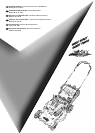
Powered Walk Behind Mower - CE Part No. 04016218 Rev G © Copyright 12/2006
™
2
ENGLISH
SPECIFICATIONS
•
This manual covers several mowers with the following specifications:
- Models 51, 61
- 20” (508mm Cut Width)
- 12 Cut Height Settings
- Model 80
- 22” (560mm Cut Width)
- 15 Cut Height Settings
NB.
- Models come with one of a range of engines (refer to the engine manual included in the kit)
- Options are available (and may be included) on the above models e.g.
- Mulch Mowing
- Deflector Mowing
- Remote Air Cleaner
- Powerstart Function
- Self Propelled Function
- etc.
- Details may be included in this manual or on a separate manual included in the Mower Kit.
SETTING UP
•
Before using the Mower the following set-ups are required:
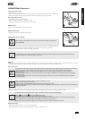
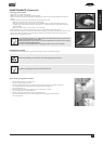
ASSEMBLY OF THE GRASS CATCHER
•
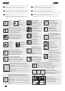
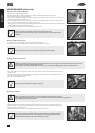
Locate the catcher handle and align its front lugs with the slots in the top of the catcher and press firmly into position
(refer figure 2).
•
Position the catcher top over the catcher bottom, aligning the barbs on the top with the slots in the bottom (refer
figure 2).
•
Press firmly down on the catcher top to lock the barbs into slots (refer figure 2).
•
Secure the top and bottom halves of the grass catcher together at the front using the two 3/16” screws, washers and
nyloc nuts supplied. Insert the screws from the outside with the washers and nyloc nuts on the inside of the catcher.
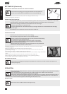
FOLDING THE HANDLE
•
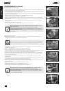
Locking knobs: by turning these knobs the handle bars can be either locked in the operating position or folded for storage.
•
Locking lever: lift the lever to release the handle bars for folding or push the lever closed to lock handle bars in the
operating position. Adjust the tension by turning the lock nut with a 1/2" AF spanner (refer figure 4 A).
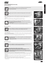
Before unfolding the handlebar, ensure the throttle control is in the stopped position (see
“Starting the Engine” section) and activate the operator presence control lever (refer figure
3). Lift the handlebar slowly (as the engine start cord is attached and it will crank the engine)
until the fully erect position is achieved.
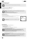
ADJUSTING THE HANDLE HEIGHT
•
Loosen the two nuts (B) at the base of the handle bars on both sides of the mower using a 1/2" AF spanner (refer figure
4).
•
Move the handle bars to the required position and tighten the handle bar nuts.
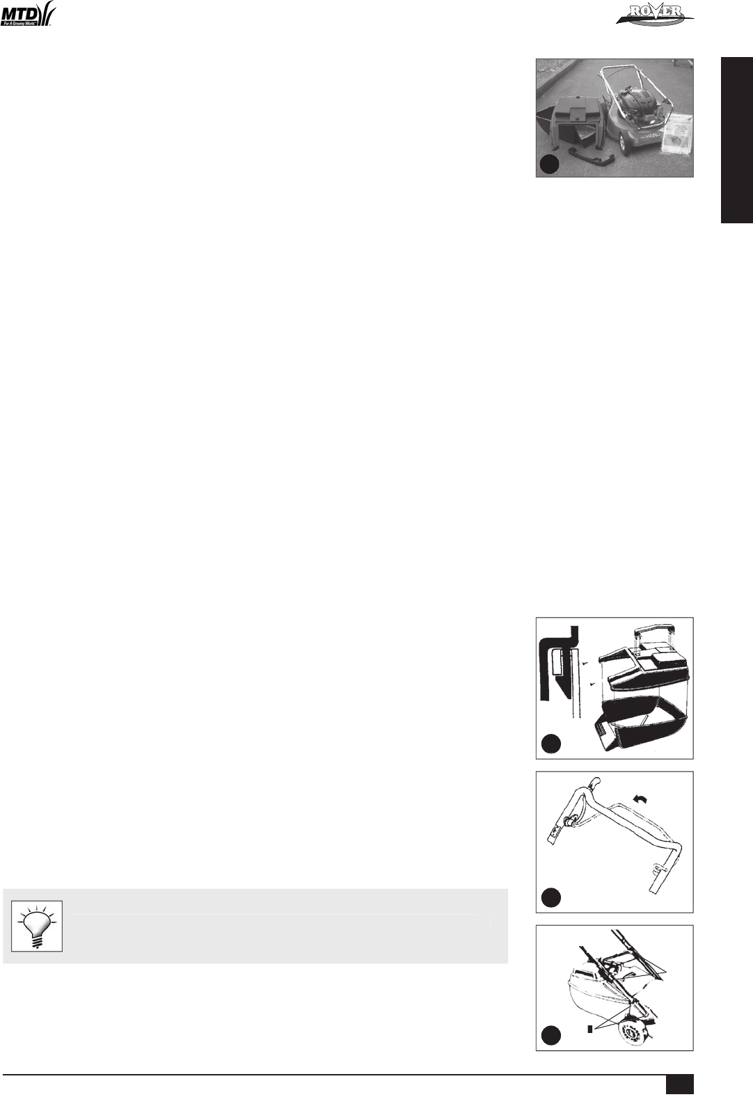
COMPONENTS
•
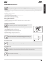
Ensure that all the following component parts are included in the package (refer figure 1):
-
Mower (1 off)
-
Kit including:
Owners Manual (1 of)
Engine Manual (1 of)
Spark Plug Spanner (1 of)
Screw - 3/16” x 1/2” UNC (2 of)
Nyloc nut - 3/16” UNC (2 of)
Washer - 3/16” x 1/2” flat (2 of)
-
Grass catcher bottom (1 of)
-
Grass catcher top (1 of)
-
Grass catcher handle (1 of - may be loose or fitted to Grass catcher top)
NB. Other accessories may be included in the carton which vary with each model. These items will be covered by a
separate owners manual e.g. Mulch Mowing Kit, Grass Deflector Kit, etc.
•
Notify the place of purchase of missing items as soon as possible.
1
2
4
B
A
3
0OWERED7ALK"EHIND!#%%NGLISHINDD